B
58
Repair and Service Manual
FRONT CV SHAFT, SUSPENSION, AND STEERING
Read all of SAFETY and this section before attempting any procedure. Pay particular attention to Notices, Cautions, Warnings and Dangers.
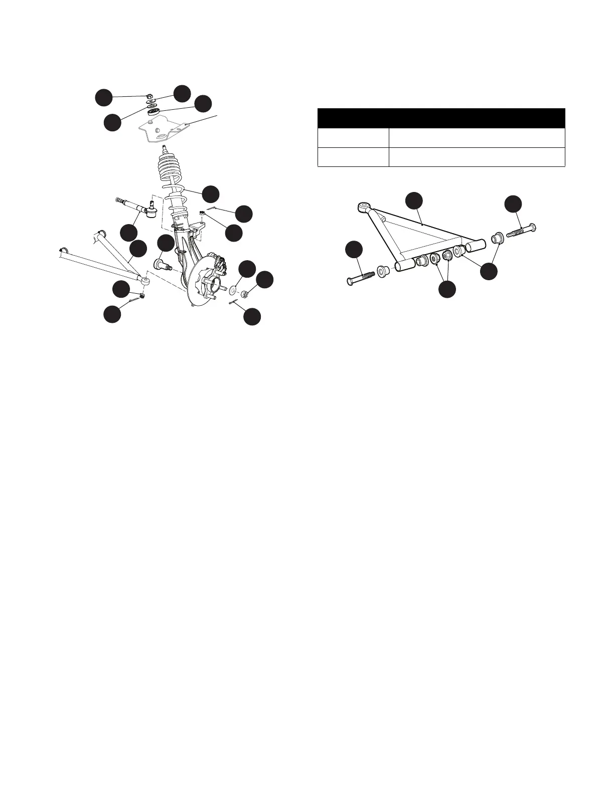
10002660
Fig. 1 Front Suspension
Control Arm Assembly Replacement
Tool List Qty.
Wheel Chocks ............................................................. 4
Floor Jack .................................................................... 1
Jack Stands ................................................................. 2
Plastic Faced Hammer ................................................ 1
Needle Nose Pliers...................................................... 1
Wrench, 9/16” .............................................................. 1
Wrench, 17mm ............................................................1
Socket, 9/16” ............................................................... 1
Socket, 17mm.............................................................. 1
Ratchet ........................................................................1
Ball Joint Separator ..................................................... 1
Torque Wrench, ft. lbs.................................................. 1
1. Lift and support the front of the vehicle (See Lift
Front of Vehicle on page 9).
2. Remove the front wheel (See WHEEL AND TIRE
SERVICE on page 128).
3. Remove the cotter pin (10) and castellated nut (9)
from the lower ball joint at the control arm assembly
(21) (Ref. Fig. 1).
4. If necessary, use a ball joint separator to separate
the control arm (21) from the strut assembly (1).
5. Remove the bolt (22), flanged bushings (19), and
lock nuts (23)
6. To remove the control arm (21) from the vehicle (Ref.
Fig. 2).
Assemble in the reverse order of removal.
Tighten hardware to torque values specified below.
Fig. 2 Control Arm
Lower Ball Joint Replacement
Tool List Qty.
Wheel Chocks..............................................................4
Floor Jack ....................................................................1
Jack Stands .................................................................2
Allen Socket, 5/32”.......................................................1
Socket, 17mm..............................................................1
Wrench, 17mm.............................................................1
Ball Joint Separator .....................................................1
Ratchet ........................................................................1
Thread Locking Adhesive, Red..........................003 mL
1. Lift and support the front of the vehicle (See Lift
Front of Vehicle on page 9).
2. Remove the front wheel (See WHEEL AND TIRE
SERVICE on page 128).
3. Remove the cotter pin (10) and castellated nut (9)
from the lower ball joint at the control arm assembly
(21) (Ref. Fig. 1).
4. If necessary, use a ball joint separator to separate
the control arm from the lower ball joint.
5. Remove the two screws (101) securing the lower ball
joint (100) to the strut assembly (1) (Ref. Fig. 3).
11
21
27
8
9
10
26
25
24
2
4
3
5
1
Part of Frame
12
Item Torque Specification
23 32 - 37 ft. lbs. (43 - 50 Nm)
9 12 - 14 ft. lbs. (16 - 19 Nm)