B
122
Repair and Service Manual
FAULT TESTING
Read all of SAFETY and this section before attempting any procedure. Pay particular attention to Notices, Cautions, Warnings and Dangers.
10002660
Fig. 20 Speed Sensor
Back probe pins are needed to perform electrical tests via
wire harness connectors.
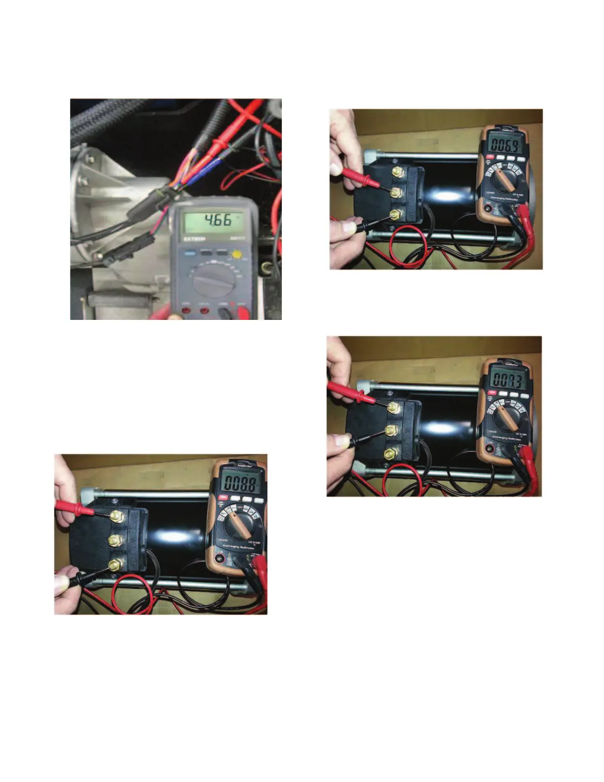
AC Motor Bench Test
Set a standard digital volt/ohm meter to the diode test
position. Make sure the audible alarm can be heard.
1. Place one meter probe on the U-terminal and the
other probe on the W-terminal. Full continuity should
be observed (Ref. Fig. 21).
Fig. 21 U and W terminal
2. Now place one meter probe on the V-terminal and
the other probe on the W-terminal. Full continuity
should be observed (Ref. Fig. 22).
Fig. 22 V and W terminal
3. Then place one meter probe on the U-terminal and
the other probe on the V-terminal. Full continuity
should be observed (Ref. Fig. 23).
Fig. 23 U and V terminal
NOTICE: If continuity is not observed between ter-
minals; an open motor field condition may exist.
Disassemble the motor to visually confirm.
4. Place one meter probe on any of the three motor ter-
minals. The other meter probe should be placed on
the motor case. No continuity should be observed
(Ref. Fig. 24).