B
118
Repair and Service Manual
FAULT TESTING
Read all of SAFETY and this section before attempting any procedure. Pay particular attention to Notices, Cautions, Warnings and Dangers.
10002660
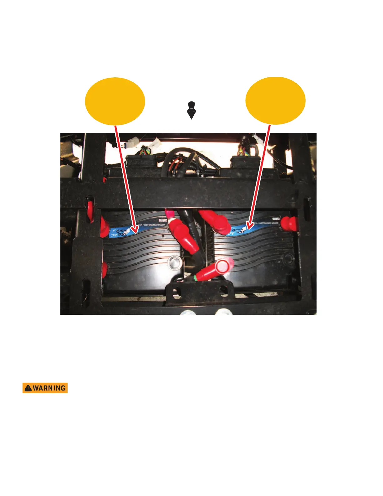
Controller Location and Mounting Configuration
Fig. 10 Controller Location and Mounting Configuration
COMPONENT TESTING
Voltmeter
Before performing any test of wiring
components, disconnect the bat-
tery cables from the battery posts to
prevent electrical shock or explo-
sion.
Electrical tests of the wiring for continuity can be done
with a DVOM (Digital Volt Ohm Meter), available through
the Service Parts Department (P/N 27481G01). The
actual model can vary depending on availability. The
DVOM (digital volt ohm meter) shown in Figure 10, is rep-
resentative only. Any DVOM can be used, however the
controls, displays and features can vary depending on the
make and model. Always follow the meter manufacturer’s
recommendations and instructions for the use and care of
meter. For the purpose of this section, the red probe as
(+) and black probe as (-) are used. Set the meter selec-
tor to the ohms scale, and check continuity between each
circuit component as indicated.
Example: If a switch is open or if there is a break in the
wiring, the meter will display a visual signal. If an analog
meter is used, it will read infinity (∞).
Rear
Motor
controller
Front
Motor
controller
Front of Vehicle
 Loading...