B
FRONT CV SHAFT, SUSPENSION, AND STEERING
Read all of SAFETY and this section before attempting any procedure. Pay particular attention to Notices, Cautions, Warnings and Dangers.
59
Repair and Service Manual
10002660
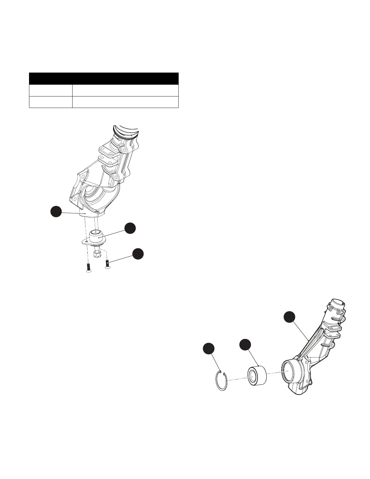
Assemble in the reverse order of removal using red
thread locking adhesive on screws (101).
Tighten hardware to torque values specified below.
Fig. 3 Lower Ball Joint
Wheel Bearing Replacement
Wheel Chocks..............................................................4
Floor Jack ....................................................................1
Jack Stands .................................................................4
Plastic Faced Hammer ................................................1
Wrench, 17mm ............................................................1
Wrench, 19mm ............................................................1
Impact Wrench.............................................................1
Impact Socket, 24mm ..................................................1
Torque Wrench, ft. lbs..................................................1
Socket, 17mm..............................................................1
Socket, 19mm..............................................................1
Ratchet ........................................................................1
Snap Ring Pliers ..........................................................1
Arbor Press..................................................................1
Hammer, Ball Peen......................................................1
Brass Punch ................................................................1
1. Lift and support the front of the vehicle (See Lift
Front of Vehicle on page 9)
2. Remove the front wheel (See WHEEL AND TIRE
SERVICE on page 128).
3. Remove the strut assembly (See Front Strut Assem-
bly Replacement on page 57).
4. Slide the hub out of the front of the strut assembly.
5. Remove the snap ring (104) securing the wheel
bearing (103) into the strut assembly (1).
6. Press the wheel bearing (103) out of the front of strut
assembly (1) from the rear.
7. If an arbor press is not available, a ball peen hammer
and brass punch can be used to tap the wheel bear-
ing out of the strut assembly.
Assemble in the reverse order of removal.
Fig. 4 Wheel Bearing
Item Torque Specification
101 95 - 105 in. lbs. (11 - 12 Nm)
9 12 - 14 ft. lbs. (16 - 19 Nm)