B
62
Repair and Service Manual
FRONT CV SHAFT, SUSPENSION, AND STEERING
Read all of SAFETY and this section before attempting any procedure. Pay particular attention to Notices, Cautions, Warnings and Dangers.
10002660
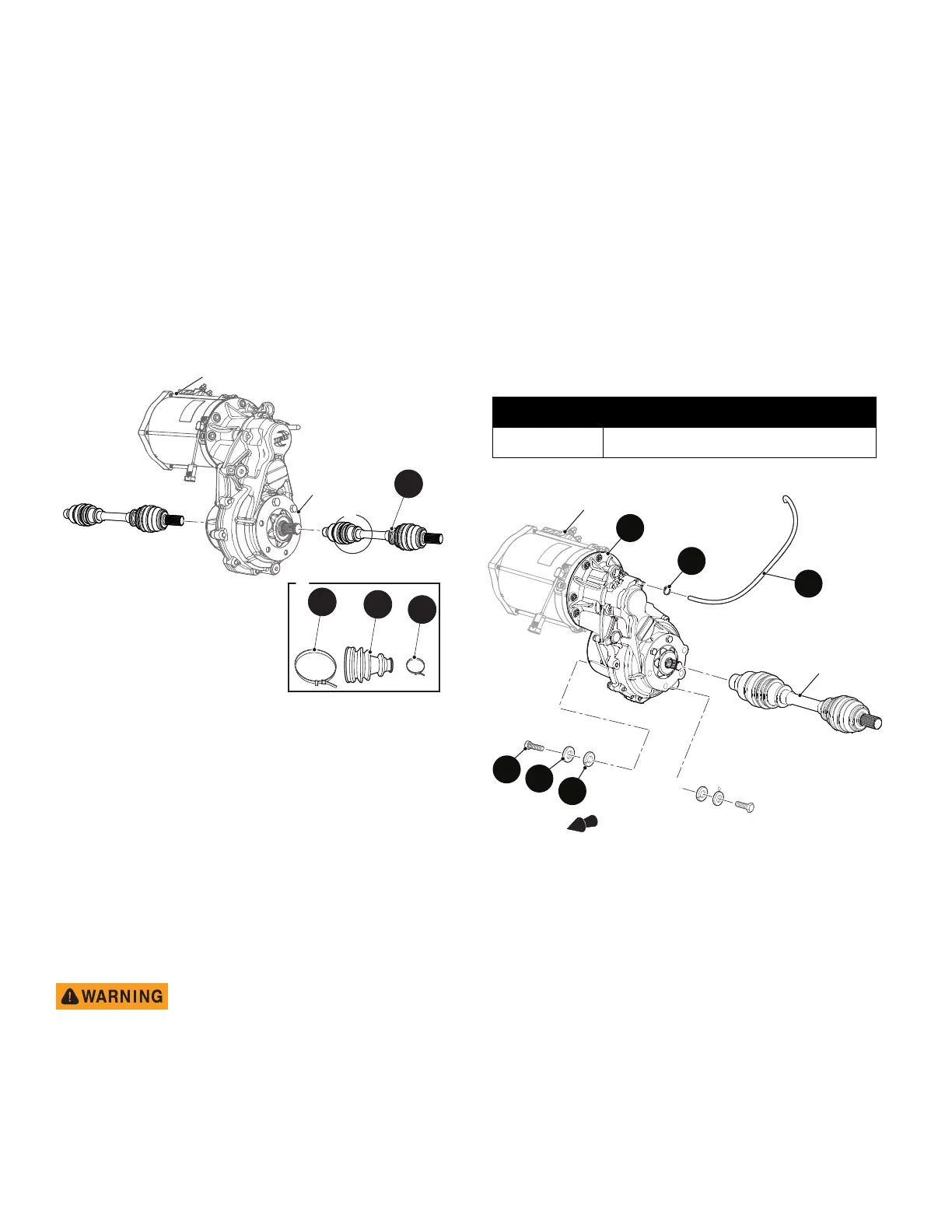
CV Joint Boot Replacement
Tool List Qty.
Needle Nose Pliers...................................................... 1
Wire Cutters................................................................. 1
1. Remove the front axle assembly. (See Front Differ-
ential Replacement on page 62)
2. Inspect the inner and outer CV joint boots (28) for
damage (Ref. Fig. 7).
3. Cut the CV joint boot clamps (29) and (30) and
remove the CV joint boot (28).
Assemble in the reverse order of removal.
Fig. 7 CV Boot Replacement
Front Differential Replacement
Tool List Qty.
Wheel Chocks ............................................................. 4
Floor Jack .................................................................... 1
Jack Stands ................................................................. 4
Impact Wrench ............................................................1
Impact Socket, 24mm.................................................. 1
Wrench, 3/4” ................................................................ 1
Plastic Faced Hammer .............................................. 11
Socket, 9/16” ............................................................... 1
Wrench, 9/16” .............................................................. 1
Torque Wrench, ft. lbs.................................................. 1
To prevent injury caused by acci-
dental movement of the differential,
you must have a second person to
help support and remove the differ-
ential.
1. Lift and support the front of the vehicle (See Lift
Front of Vehicle on page 9).
2. Remove the front wheel(See WHEEL AND TIRE
SERVICE on page 128).
3. Remove the CV shaft. (See CV Shaft Replacement
on page 61)
4. Remove the motor (See Front Motor Removal on
page 70).
5. Remove the breather hose (34) by removing the
clamp (35) and set aside for reuse during installation.
6. Remove the eight bolts (31), lock washers (33) and
flat washers (32).
7. Carefully lift the differential (30) from vehicle (Fig. 8).
Assemble in the reverse order of removal.
Tighten hardware to torque values specified below.
Fig. 8 Front Differential Replacement
Item Torque Specification
31 30 - 35 ft. lbs. (41 - 47 Nm)
1
34
Front of Vehicle
Motor
CV Shaft
30
31
32
33
35