B
36
Repair and Service Manual
BRAKES
Read all of SAFETY and this section before attempting any procedure. Pay particular attention to Notices, Cautions, Warnings and Dangers.
10002660
Complete brake failure usually indicates a loss of hydrau-
lic fluid pressure.
If the brake pedal has a soft feel:
1. Bleed the brakes to remove air from the brake sys-
tem. (See BLEEDING AND FLUSHING on page 38)
A brake pedal that loses resistance indicates a leak in the
hydraulic system:
1. Check brake fluid level.
2. If the fluid is low, inspect the system for leaks.
i. Check for leaks by applying pressure to the
pedal gradually and steadily.
ii. If pedal sinks very slowly to the floor, the sys-
tem has a leak along the brake lines or at the
hydraulic cylinder. If no external leaks are
apparent, the problem is likely inside the
master cylinder
3. If leaks are found, repair the leaks in the brake sys-
tem.
4. If the master cylinder is found to be leaking, replace
it.
5. Bleed the brakes to remove air from the brake sys-
tem.
Do not allow brake fluid to contact
painted surfaces. Wipe off immedi-
ately if contact is made.
MASTER CYLINDER
The master cylinder is mounted to the frame, behind the
driver side front wheel (Ref. Fig. 1). The master cylinder
will eventually require replacement due to deterioration of
the cylinder seals (cups). Fluid will leak past the cups and
show as an external leak. A common symptom is a soft
brake pedal, meaning that it goes all the way to the floor.
The rubber parts wear or deteriorate with use, age, or
fluid contamination. Corrosion or deposits formed in the
cylinder bore that are due to moisture or dirt in the
hydraulic system may cause wear of the cylinder bore or
related parts. Do not try to remove corrosion or deposits
with a cylinder hone. If corrosion or deposits are detected
on the master cylinder, replace it with a new one and flush
the system (See Flushing on page 39).
Master Cylinder Replacement
Tool List Qty.
Insulated Wrench, 9/16” .............................................. 1
Container ..................................................................... 1
Needle Nose Pliers...................................................... 1
Wrench, 9/16” .............................................................. 2
Wrench, 1/2” ................................................................ 1
Wrench, 14mm ............................................................1
Socket, 9/16” ............................................................... 1
Socket, 1/2” ................................................................. 1
Socket, 14mm.............................................................. 1
Torque Wrench, ft. lbs.................................................. 1
DO NOT reuse crush washers.
When replacing the master cylin-
der, it is likely that brake fluid will
leak from the master cylinder. Do
not allow brake fluid to contact the painted body
components of the vehicle. Clean off immediately if
contact is made.
1. Switch the key switch into the OFF position, and
remove the key.
2. Clean the area around the master cylinder (1) to pre-
vent dirt and grease from contaminating the hydrau-
lic system (Ref. Fig. 2).
3. Remove the banjo bolts (9) and washers (10).
4. Disconnect the front brake line (7) and the rear brake
line (11) from the master cylinder (1) (Ref. Fig. 2).
Provide a container for the released brake fluid.
5. Remove the cotter pin (3) and clevis pin (4).
6. Remove two hex head bolts (2) and nuts (5).
7. Remove the master cylinder from the vehicle.
Assemble in the reverse order of removal using new
crush washers. Tighten all hardware to the torque values
specified below.
.
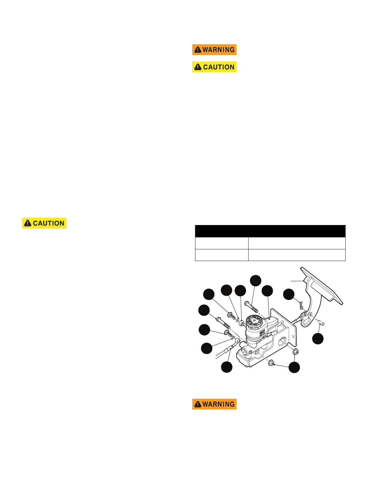
Fig. 2 Master Cylinder
To prevent contaminated brake fluid
causing a brake failure, never use
any excess fluid or return to the
original container. Dispose of brake
fluid properly.
Item Torque Specification
9 20 - 24 ft lbs. (27- 32 Nm)
5 13 - 17 ft. lbs. (18 - 23 Nm)
5
4
3
2
9
2
11
1
9
10
Brake
Pedal
7
10