B
54
Repair and Service Manual
ELECTRICAL
Read all of SAFETY and this section before attempting any procedure. Pay particular attention to Notices, Cautions, Warnings and Dangers.
10002660
Rocker Switches
Tool List Qty.
Screwdriver, Flathead.................................................. 1
Bit Driver...................................................................... 1
Torx Bit, T30 ................................................................1
Pliers, Needle Nose.....................................................1
1. Disconnect the negative battery cable using an insu-
lated wrench.
2. Remove the gauge panel (See Gauge Panel
Replacement on page 24)
3. Disconnect the main wiring harness from the rocker
switch.
4. Squeeze the tabs on the top and bottom of the back-
side of the rocker switch (43) and push it through the
front of the gauge panel (40) (Ref. Fig. 17).
Assemble in the reverse order of removal. Confirm proper
orientation of the switch prior to seating it completely in
the gauge panel.
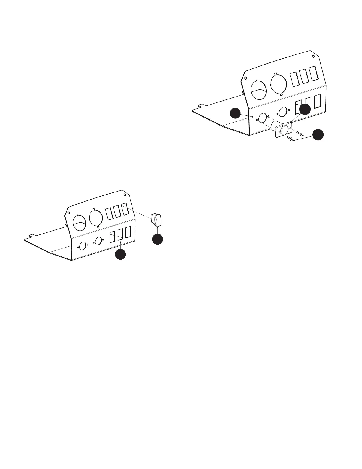
Fig. 17 Rocker Switch12V Outlet
NOTICE: It is not necessary to remove the gauge
panel to replace the 12V outlet.
Tool List Qty.
Drill ..............................................................................1
Drill Bit ......................................................................... 1
Rivet Gun
1. Drill out the two rivets securing the 12V outlet (45) to
the gauge panel (40).
2. Gently pull the 12V outlet (45) through the front of
the gauge panel (40) until the push on connectors
are accessible.
3. Disconnect the push on connectors.
4. Connect the push on connectors to the new 12V out-
let.
5. Install the 12V outlet into the gauge panel using new
rivets (Ref. Fig. 18).
Fig. 18 12V Outlet