28
CVHE-SVX005C-EN
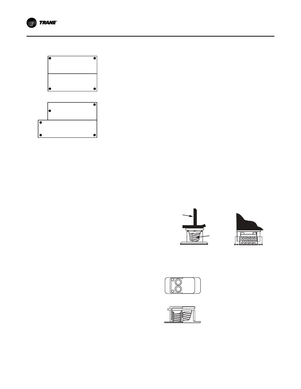
Figure 7. Isolation spring placement by shell size,
and evaporator and condenser length
Condenser
Evaporator
Condenser
Evaporator
left
rear
left
front
right
rear
right
front
left
rear
right
rear
left
center
right
front
left
front
032 S/S, S/L, L/L
050 S/S, S/L, L/L
080 S/S, S/L, L/L
142 M/L, L/L
210 L/L
142 E/L
250 E/L
Spring isolators typically ship assembled and ready for
installation. To install and adjust the isolators properly,
follow the provided instructions.
Note: Do NOT adjust the isolators until the chiller is piped
and charged with refrigerant and water.
Important: Do NOT block any serviceable components
such as the lubrication system with field-
installed devices such as spring isolators.
1. Position the spring isolators under the chiller as shown
in the preceding figure. Ensure that each isolator is
centered in relation to the tube sheet.
Note: Spring isolators shipped with the chiller may not
be identical. Compare the data provided in the
unit submittal package to determine proper
isolator placement.
2. Set the isolators on the sub-base; shim as necessary to
provide a flat, level surface at the same elevation for
the end supports.
Important: Support the full underside of the isolator
base plate; do NOT straddle gaps or small
shims.
3. If required, screw the isolators to the floor through the
slots provided, or cement the pads.
Note: Fastening the isolators to the floor is not
necessary unless specified.
4. If the chiller must be fastened to the isolators, insert
cap screws through the chiller base and into holes
drilled and tapped in the upper housing of each isolator.
Important: Do NOT allow the screws to protrude below
the underside of the isolator upper
housing, or interfere with the adjusting
screws. An alternative method of fastening
the chiller to the isolators is to cement the
neoprene pads.
5. Set the chiller on the isolators; refer to “Standard Chiller
Lift,” p. 25. The weight of the chiller will force down the
upper housing of each isolator, and could cause it to
rest on the isolator’s lower housing (refer to the
following figure).
6. Check the clearance on each isolator. If this dimension
is less than 1/4 in. (6.35 mm) on any isolator, use a
wrench to turn the adjusting screw one complete
revolution upward.
Note: When the load is applied to the isolators (refer to
Step 5), the top plate of each isolator moves
down to compress the springs until either the
springs support the load or the top plate rests on
the bottom housing of the isolator. If the springs
are supporting the load, screwing down on the
adjusting screw (refer to Step 7) will raise the
chiller.
7. Turn the adjusting screw on each of the remaining
isolators to obtain the required minimum clearance of 1/
4 in. (6.35 mm).
8. Once the minimum required clearance is obtained on
each of the isolators, level the chiller by turning the
adjusting screw on each of the isolators on the low side
of the unit. Work from one isolator to the next.
Important: The chiller must be level to within 1/16 in.
(1.6 mm) over its length and width, and the
clearance of each isolator must be at least
1/4 in. (6.35 mm).
Figure 8. Chiller foot and isolator orientation
Side View of Unit End View of Unit
Center
tube sheet
support leg
Outside
edge of
tube sheet
Center of
isolator
spring
Note: The spring isolator must be
centered in relation to the tube sheet.
Do not align the isolator with the flat
part of the chiller foot since the tube
sheet is often off center.
Note: The length of the
isolator should be parallel
to the leg.
Important: Do NOT install spring isolators or brackets in
such a way that they could inhibit chiller
servicing such as charging or evacuation, oil
tank service, etc.
Installation: Mechanical
 Loading...


