58 Installation (for qualified installers only)
© Travis Industries 3/13/18 - 1474 42 & 54PB GSB2 Aust.
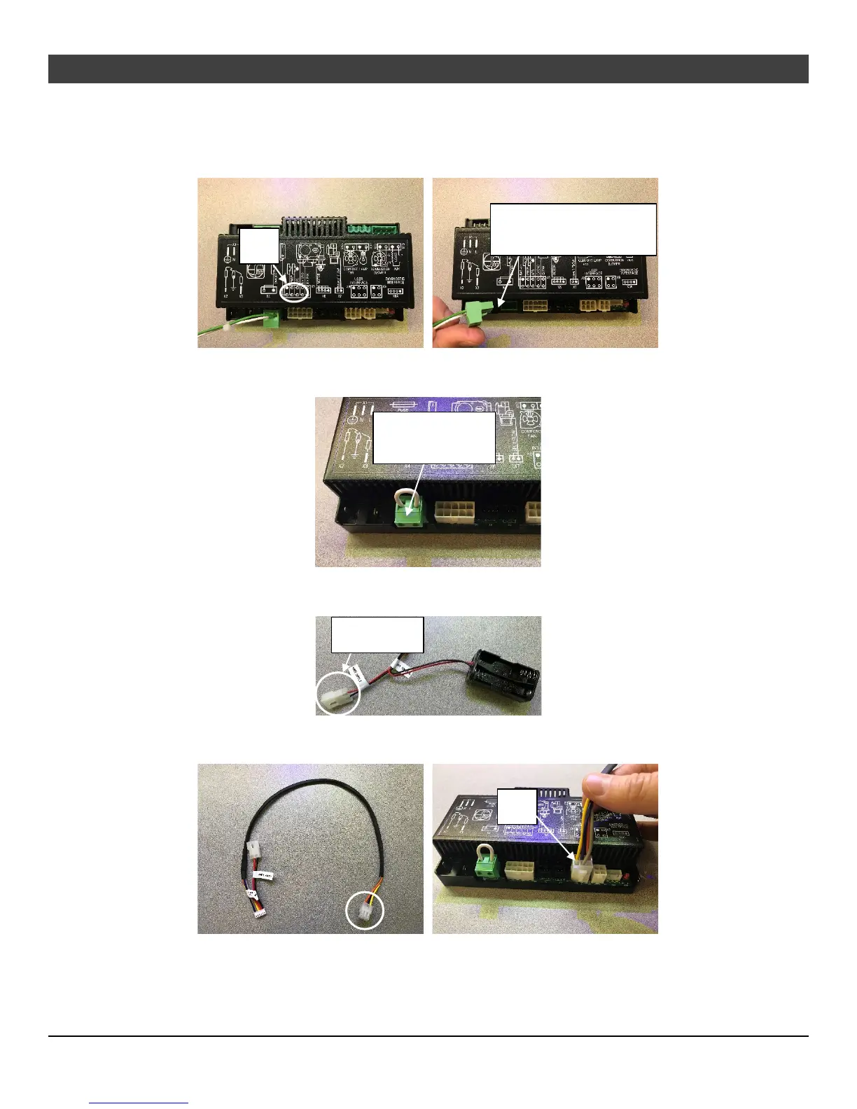
5 Follow the green and white wires to where they attach to the control module. Disconnect the green,
plastic connector from the control module by lifting straight up (location is marked X4 on the module).
Remove the connector and wires from the unit and discard. Install the switch blank into the empty
mounting hole of the switch that was removed.
6 Install the system jumper into the same location on the board that you removed the green connector
in the previous step.
7 Locate the battery holder on the appliance. Disconnect the wires at the plastic Molex connector that
connect the battery holder to the appliance wiring harness. Discard the battery holder.
8 Run the end of the included wire harness with (4) wires to the control module. Insert the connector
into the “X8 User Interface” location on the module.
X4
Remove and discard
harness and connector
Replace with
included jumper
X8
Disconnect