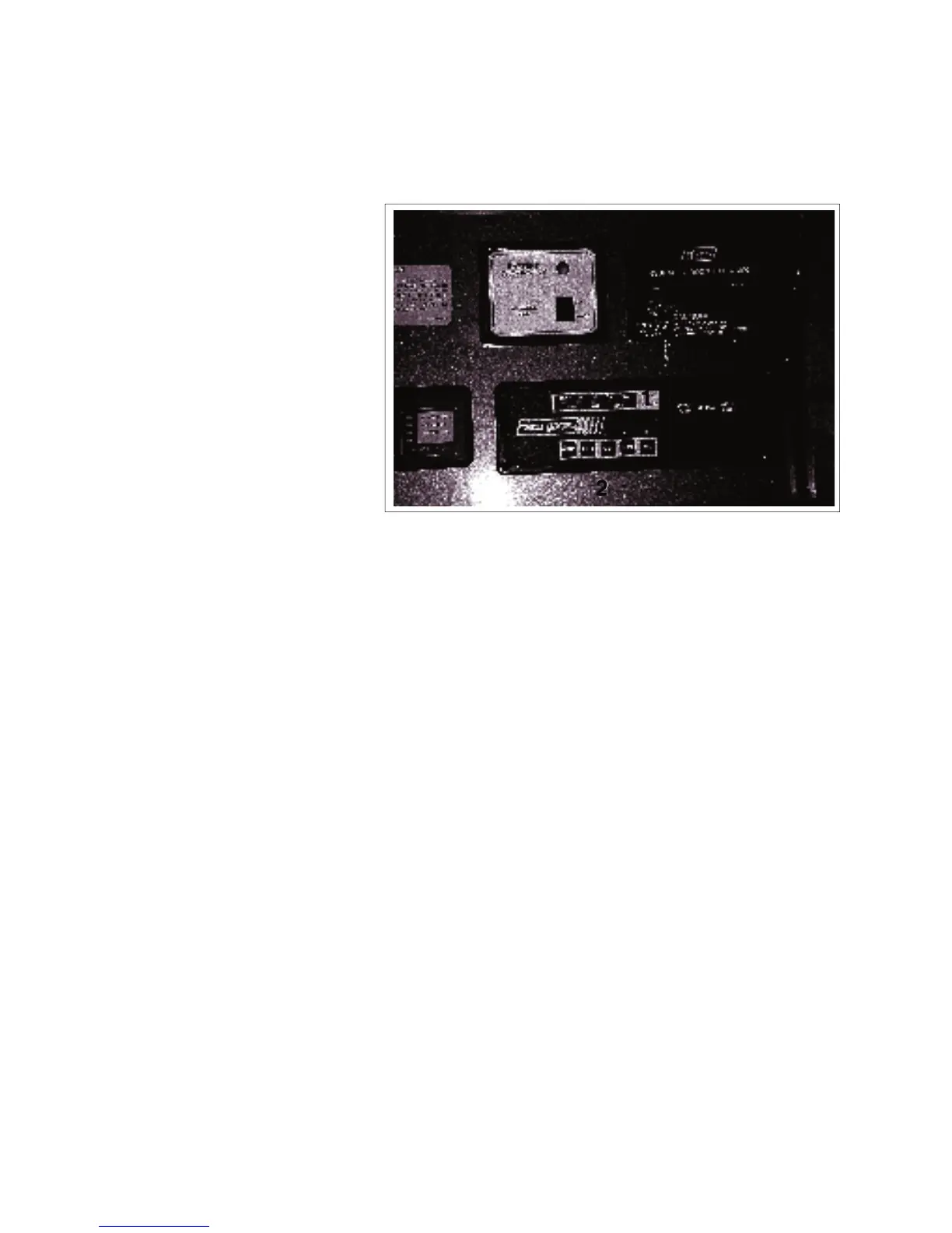
A system monitor is located on the wall next to the doorway.
Five LED's are used to indicate
the status of the tanks and bat-
tery. The tank scale registers
EMPTY, 1/4, 1/2, 3/4 or FULL.
The battery charge condition reg-
Read the appropriate scale when
the battery or tank switches are
Each system is equipped with a
switch to activate its own monitor-
ing system. Depress and hold the
switch. The system condition will
be shown by the LEDs above.
This rocker switch controls the power to the
water pump. Depress the top portion of the
switch to turn the power to the pump on. A red
light in the switch will come on when the power
is on. Depress the bottom portion of the switch
to turn off and the light will go off. When the
power is on, the auxiliary water pump switches
can be used to turn the pump on and off (Com-
mander only). See 4.15.3 for more information.
This 3 position rocker switch controls the
power to the auxiliary generator.
Depress the top portion of the switch
against the spring load to engage the
starter and start the engine. Release the
switch when the engine starts and it will
return to the run position.
Depress the bottom portion of the switch
and hold until the generator stops. Re-
This rocker switch controls the electrical power
to the water heater igniter. Depress the top
part of the switch and the water heater will ig-
nite. The red light in the switch will go off when
The red light will remain on if the burner fails to
COMMANDER / EMBASSY
a
b
e
c
d
3
4 5