Installing the System MicronNav System
0656-SOM-00001-07 22 © Tritech International Ltd.
change these default settings of a Micron Responder without first seeking help
and advice from Tritech International Ltd.
Ensure the Tritech International Ltd Sonar has been installed on the ROV as detailed in the
appropriate product manual. Install the MicronNav sub-sea Modem Head on the ROV as
detailed in Section 3.1.2, “Mounting the Subsea Modem Head” and checking the connector
threads are clean and contacts dry carefully connect the main connector port of the modem
head to the auxiliary connector port of the sonar head using the double ended interconnect
lead.
Ensure the blanking cap on the auxiliary port of the modem head is fitted.
Connect the top side communications to the appropriate port on the rear of the MicronNav100
Interface Hub using the previously wired cable as detailed in Section 3.1.6, “Electrical
Connection to the Surface MicronNav100 Interface Hub”.
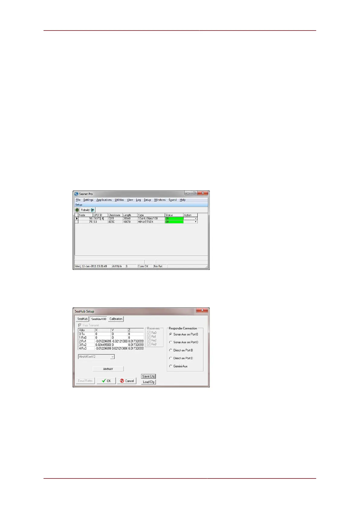
Switch on the power supply to the MicronNav100 Interface Hub and click the Seanet Setup
icon on the desktop, if the Surface Hardware installation and configuration has been carried
out correctly the SEAHUBNAV100 (Node 90) and MINIATTSEN (Node 75) should appear in
the device list.
The system now needs to be configured in order for it to correctly operate the
Micron Responder. The exact method will depend on how the Micron Responder
has been connected. Open the Setup page of Node 90, click on the SeaNav100
tab and then select the method being used to connect the MicronNav Responder.