LIST OF FIGURES
Figure Title Page
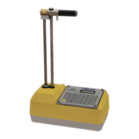
1–1 3440 Gauge and Standard Accessories.................................. 1–5
1–2 3440 Keypad Layout ............................................................. 1–7
2–1 3440 Gauge Showing Rod Positions ................................... 2–14
2–2 Gauge Position on Reference Standard Block ..................... 2–15
3–1 Drill Rod and Extraction Tool with Scraper Plate ................. 3–2
3–2 Marking the Test Area........................................................... 3–3
5–1 Gauge and Reference Standard Block Position for Trench
Offset ................................................................................... 5–11
5–2 Serial Port Location ............................................................. 5–18
5–3 Sample Project Printouts ..................................................... 5–20
5–4 Calculator Function Keys .................................................... 5–24
6–1 Stat Test Printout Sample ...................................................... 6–6
6–2 Drift Test Printout Sample .................................................... 6–8
A–1 Direct Transmission Geometry ............................................ A–2
A–2 Backscatter Geometry .......................................................... A–3
A–3 Depth of Top Layer .............................................................. A–4
A–4 Effect of Moisture on Depth of Measurement ...................... A–7
B–1 Diagram of an Atom .............................................................. B–2
B–2 Variation of Radioactive Emission. ....................................... B–4
C–1 Effect of Distance on Exposure ............................................. C–3
C–2 3440 Gauge and Transport Case............................................ C–4
D–1 Sample Notice to Employees ............................................... D–6
F–1 Retaining and Scraper Rings ................................................. F–5
F–2 3440 Baseboard Assembly .................................................... F–9
F–3 3440 Gauge Assembly (Sheet 1 of 2) .................................. F–16
F–4 3440 Base Mechanical Assembly ........................................ F–20
F–5 3440 Source Rod Handle Assembly .................................... F–20
F–6 3440 Preamplifier Assembly ............................................... F–22
F–7 3440 Front Panel Assembly ................................................ F–24