TRUE ICE SERVICE MANUAL
TEC_TM_198 | REV. A | EN 03/26/2024 Page 73 of 96
truemfg.com
Troubleshooting & Diagnosis (cont.)
Water Level Sensor
The water level sensor uses pneumatic technology to sense
pressure changes determined by the water level in the sump tank.
Those pressures are then converted into millimeters of water and
are displayed on the information screen.
1. Turn the unit off at the touchscreen.
2. Remove the drain fitting located under the sump tank. This will
allow all the water to drain into the bin or dispenser.
3. Press the info button
to open the information screen.
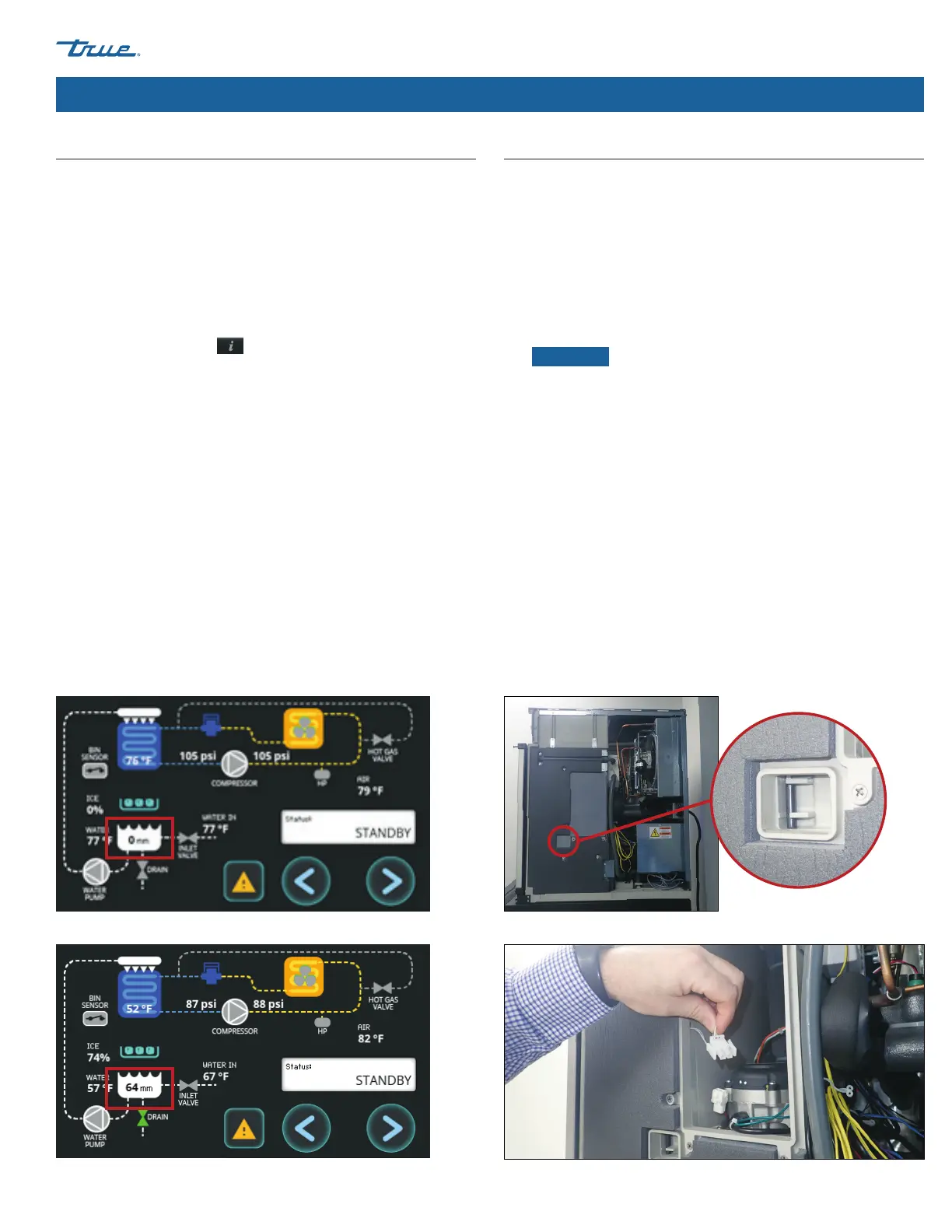
4. On the information screen, verify the water level is reading 0
mm (+/-2mm). See fig. 1.
5. Disconnect power to the drain valve, reattach the sump drain
fitting, and fill the sump tank with water until water overflows
into the bin or dispenser.
6. On the information screen, verify the water level is reading 63
mm (+/-2mm). See fig. 2.
7. If the display is reading the correct water levels, then the
sensor is working correctly. If the display is not reading the
correct water levels, check the tubing connections on the
sensor and the board for any possible air leaks or kinks in the
tubing.
8. If no issues are found, replace the control board.
Proximity Switch (Bin Switch)
1. Turn the unit off at the touchscreen.
2. Remove the top and right side panels. See “Panel Removal”
(pg. 49).
3. Remove the rubber covers.
4. Locate the proximity switch (bin switch). See fig. 1.
5. Disconnect the proximity switch molex connector. See fig. 2.
Then, insert meter test leads.
NOTICE ›
Pull the damper away from the closed position 50
times. If the meter reading is not consistent every time, then
replace the proximity switch.
• With the damper in the closed position, the resistance
reading should be 0 Ω.
• With the damper in the open position, the resistance reading
should be O.L..
6. Disconnect power to the unit.
7. Unplug the proximity switch connector from the board and
ohm the wire harness (with the damper closed, it should read
0 Ω).
• If the wire harness DOES NOT read 0 Ω, replace the wire
harness.
• If the wire harness reads 0 Ω, replace the control board.
Fig. 1. The water level reads 0 mm. Fig. 1. Proximity switch (bin switch) location.
Fig. 2. The water level reads 63 mm +/- 2 mm. Fig. 2. Proximity switch molex connector (disconnected).
 Loading...