Mover smart M RS1 Installation
27EN
60040-00463 ∙ 00 ∙ 09/2023
sure that the grippers remain correctly positioned
1
Fig� 36
1 Mounting
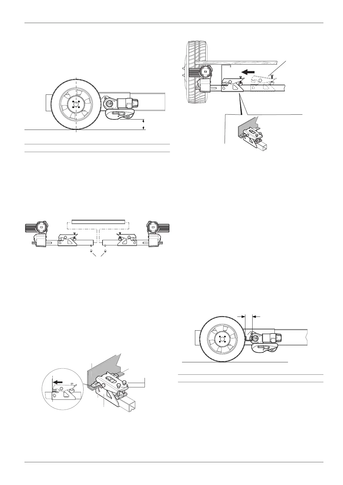
6.1.5 Adjust the distance between the tyres and
drive rollers
NOTICE
Damage due to incorrect distance between
the tyres and drive roller
If the distance is too small, the tyres and the
manoeuvring system may be damaged�
If the distance is too great, safe transmission of
power to the tyres is not possible and the cara-
van can become uncontrollable�
Ensure that the distance between the tyre
and the disengaged drive roller is 20 mm�
Set the correct distance (Fig� 37-a) between the tyres
and drive roller using the spacer plate supplied by
moving the drive units lengthways� The movable
connection pipe makes it possible to adjust to the
frame width� The weight of the caravan must be
resting on the wheels when doing this�
a
Fig� 37
a 20mm
Maintain a distance of at least 10mm between the
gear housing and tyres/shock absorbers�
The minimum distance with the drive rollers engaged is
10 mm�
6.1.2 Observe ground clearance
Make sure that there is adequate ground clearance
(at least 110mm)�
If the minimum ground clearance cannot be ob-
served, it is not possible to install a manoeuvring
system�
a
Fig� 33
a min�110mm
6.1.3 Attach the drive units to the connection
pipe
Mark connection pipe in the centre�
Loosely attach the drive units to the connection
pipe�
Do not yet screw in the threaded bolts included in
the scope of (Fig� 34-1) delivery�
1
Fig� 34
1 Threaded bolts
6.1.4 Positioning the drive units and mounting
Place the drive units together with the connec-
tion pipe and the mounting system(Fig� 35-2)
on the vehicle frame and tighten using the two
screws(Fig� 35-3) so that it is just possible to move
them on the frame�
The gripper (Fig� 35-1) must lie completely flat against
the vehicle frame (Fig� 35-4) and also flat against the leg
(Fig� 35-5)�
3
1
2
5
4
Fig� 35
The drive rollers must cover the maximum tread area
of the tyres in the lateral direction�
Move the drive units sideways accordingly and en-
 Loading...