Mover smart M RS1Installation
28 EN
60040-00463 ∙ 00 ∙ 09/2023
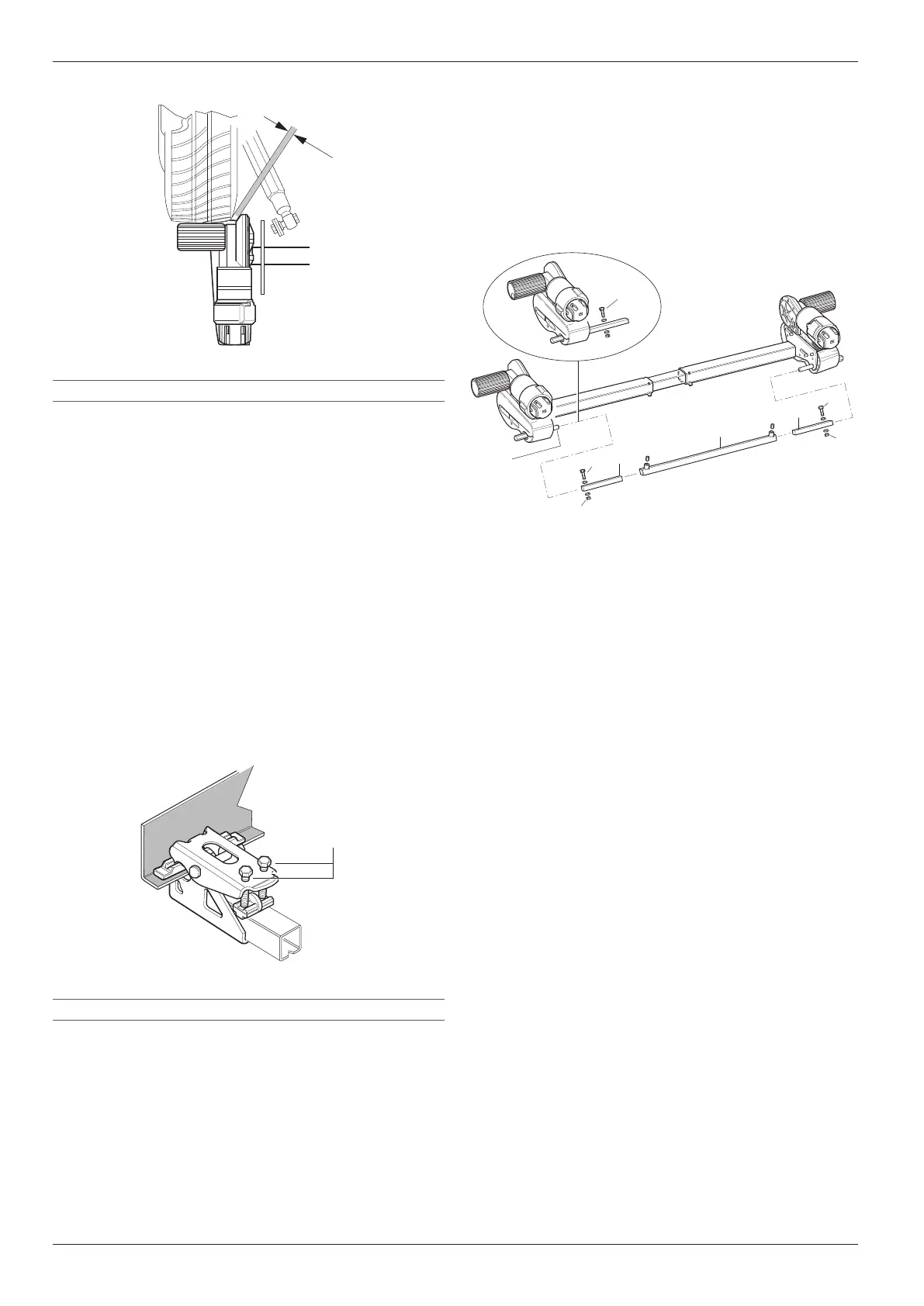
Insert the screws (Fig� 40-5) through the toggle
crank� Tighten with the nuts (Fig� 40-4) (10Nm ±
1Nm)�
Centre the long square pipe (Fig� 40-2) measuring
again if necessary�
Screw in the 2threaded bolts (Fig� 40-3) in this posi-
tion (15Nm)�
Finally, check all the bolted connections again�
4
2
3
1
6
5
5
3
4
5
1
Fig� 40
1 Square pipe, short
2 Square pipe, long
3 Threaded bolt
4 Nut
5 Screw
6 Toggle crank
Engage the rollers using the lever provided� The
drive rollers should now be engaged on both sides�
Also check the opposite side�
Disengage the drive rollers again�
Repeat this procedure on the opposite side�
6.2 Electrical wiring and control unit
WARNING
Personal injury due to incorrectly laid or
connected cables
If cables are not laid correctly or are cut too
short, this can lead to injury or can damage the
manoeuvring system�
The drive motors move when operating�
Loosely fasten the cables from the drive
motor to the control unit to avoid stretching
them�
No cable must be laid over the control unit�
WARNING
Injury to eyes from chips during drilling
When drilling the holes on the caravan floor
through which to pass the wiring looms, flying
chips can get into the eyes and cause injury�
Wear safety glasses when drilling�
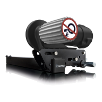
a
Fig� 38
a min� 10mm
6.1.6 Checking the distances
Once the screws (Fig� 35-3) have been placed cor-
rectly, tighten them slightly�
Then check the required distances again� The weight
of the caravan must be resting on the wheels when
doing this�
6.1.7 Fixing the connection pipe in place
Place the movable connection pipe in the middle
(mark the position) and secure each side with one
threaded bolt M8x12 (15Nm)�
6.1.8 Fixing the mounting in place permanently
Re-check the distance of 20mm from the tyre (with
the wheels under load)�
Then tighten the screws of the mounting (M10) alter-
nately in several steps to 25Nm�
a
Fig� 39
a 25Nm
6.1.9 Fitting the cross actuation device
Make sure that the drive rollers are not resting on
the tyres (on both sides)�
Push the short square pipes (Fig� 40-1) into the long
square pipe with the holes facing (Fig� 40-2) out-
wards�
Now place the short square pipes (Fig� 40-1) on the
toggle crank (Fig� 40-6)�

 Loading...