Mover smart M RS1 Preparing for installation
25EN
60040-00463 ∙ 00 ∙ 09/2023
•
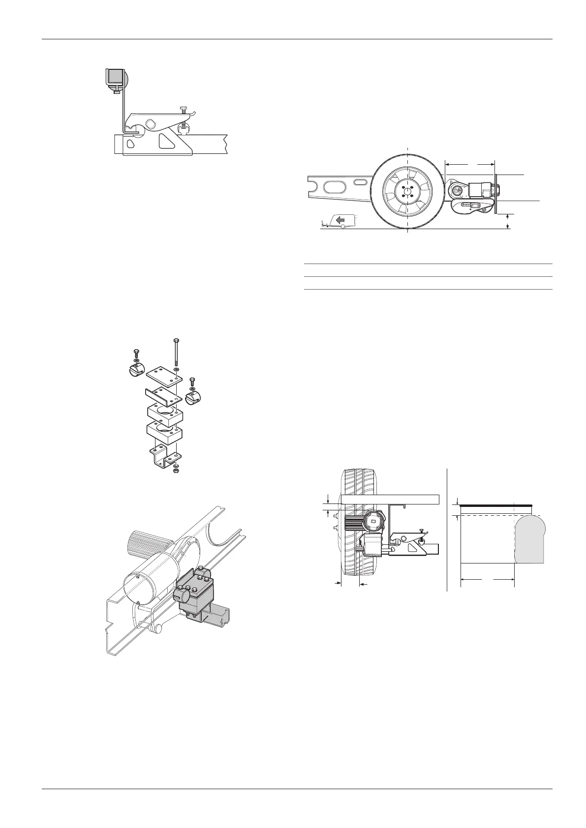
If the original mudflaps cannot be used, the Truma
mudflap kit (part no� 60031-08200) must be used
and adapted�
•
The distance from the tyres to the mudflaps must
not exceed 300mm�
•
The distance from the floor to the mudflaps must not
exceed 200mm�
b
a
Fig� 30
a max� 300mm
b max� 200mm
5.5.1 Adapting the mudflaps
For the mudflaps, the shape of the manoeuvring system
must be cut out so that the manoeuvring system is not
obstructed when engaging or disengaging�
Remove existing mudflaps�
Install the manoeuvring system in accordance with
the installation instructions (see Chapter 6)�
Cut out the template illustrated on the last pages of
the installation instructions�
Determine dimensions a and b and transfer to mud-
flaps� The top leg of the fastening bracket must face
towards the rear of the caravan�
a
b
b
a
Fig� 31
Place the template on the mudflaps� Pay attention to
the left and right sides�
Transfer the contour and cut out�
If necessary, make recesses in the mudflaps for the
apron contour�
5.6 Assembly planning
Determine the installation location for the following
components:
•
Battery
•
Control unit
•
Battery cut-o switch
•
Cable laying (floor opening)
Fig� 27
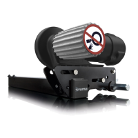
5.4.12 Short mounting system
For L-profile chassis and with a limited amount of
space, such as substructures or projecting edges, the
short mounting system is used�
The short mounting system is a replacement for the
factory-fitted standard mounting system�
The two spacer plates, which are each 30mm thick,
can compensate for a distance of either 30mm or
60mm�
•
The mounting system can be fitted in front of or
behind the axle�
•
Part No� 60031-20000
Fig� 28
Drawing serves as an example
Fig� 29
5.5 Mudflaps
•
The mudflaps are installed behind the axle� No mud-
flaps are required in front of the axle�
•
In some cases installation of the mudflaps is not
possible because of the design of the sub-frame�
•
When installing the manoeuvring system, the exist-
ing mudflaps may need to be relocated or adapted�

 Loading...