Mover smart M RS1 Installation
31EN
60040-00463 ∙ 00 ∙ 09/2023
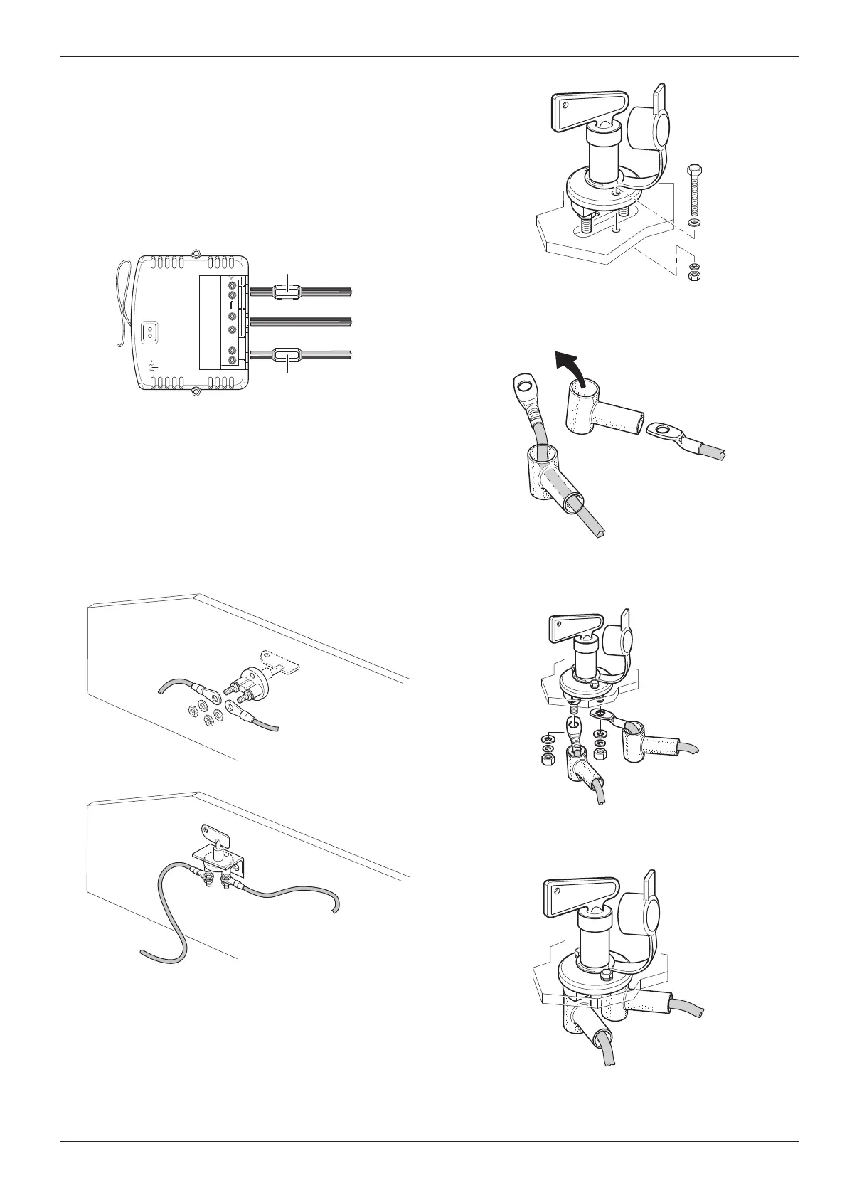
Fig� 48
Feed cable connections through protective rubber
caps (Fig� 49)�
Fig� 49
Connect the cables to the battery cut-o switch and
secure with nuts (Fig� 50)�
Fig� 50
Slide protective rubber caps on to connection
screws( Fig� 51�)
Fig� 51
Surplus cable must be laid without loops in serpen-
tine lines and must not be shortened�
After connecting and laying the cables, press the
cover flap down until it locks into place�
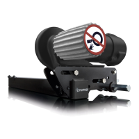
Snap ferrites
Install the two snap ferrites in the immediate vicinity
of the control unit in such a way that the red and
black cables of a motor pass through each�
1
1
Fig� 45
6.3 Connecting the battery cut-o
switch
•
The battery cut-o switch must be installed in the
positive cable between the fuse and the control unit�
•
The installation location must be easily accessible for
the user at all times (e�g� near the entrance)�
Select a suitable mounting option for the battery cut-
o switch (see installation examples Fig� 46, Fig� 47)�
Fig� 46
Fig� 47
Install the battery cut-o switch at a suitable lo-
cation inside the vehicle and fix in place using the
screws supplied (Fig� 48)�
 Loading...