EasyManuals Logo

Truma Mover smart M RS1 User Manual

Truma Mover smart M RS1
To Next Page IconTo Next Page
To Previous Page IconTo Previous Page
Page #30 background imageLoading...
Page #30 background image
Mover smart M RS1Installation
30 EN
60040-00463 ∙ 00 ∙ 09/2023
A B
RDBK BKRD
M1+ M1- M2+M2-
Fig� 43
Installation behind axle
Top view
A
B
RDBKBKRD
M1+ M1- M2+M2-
Fig� 44

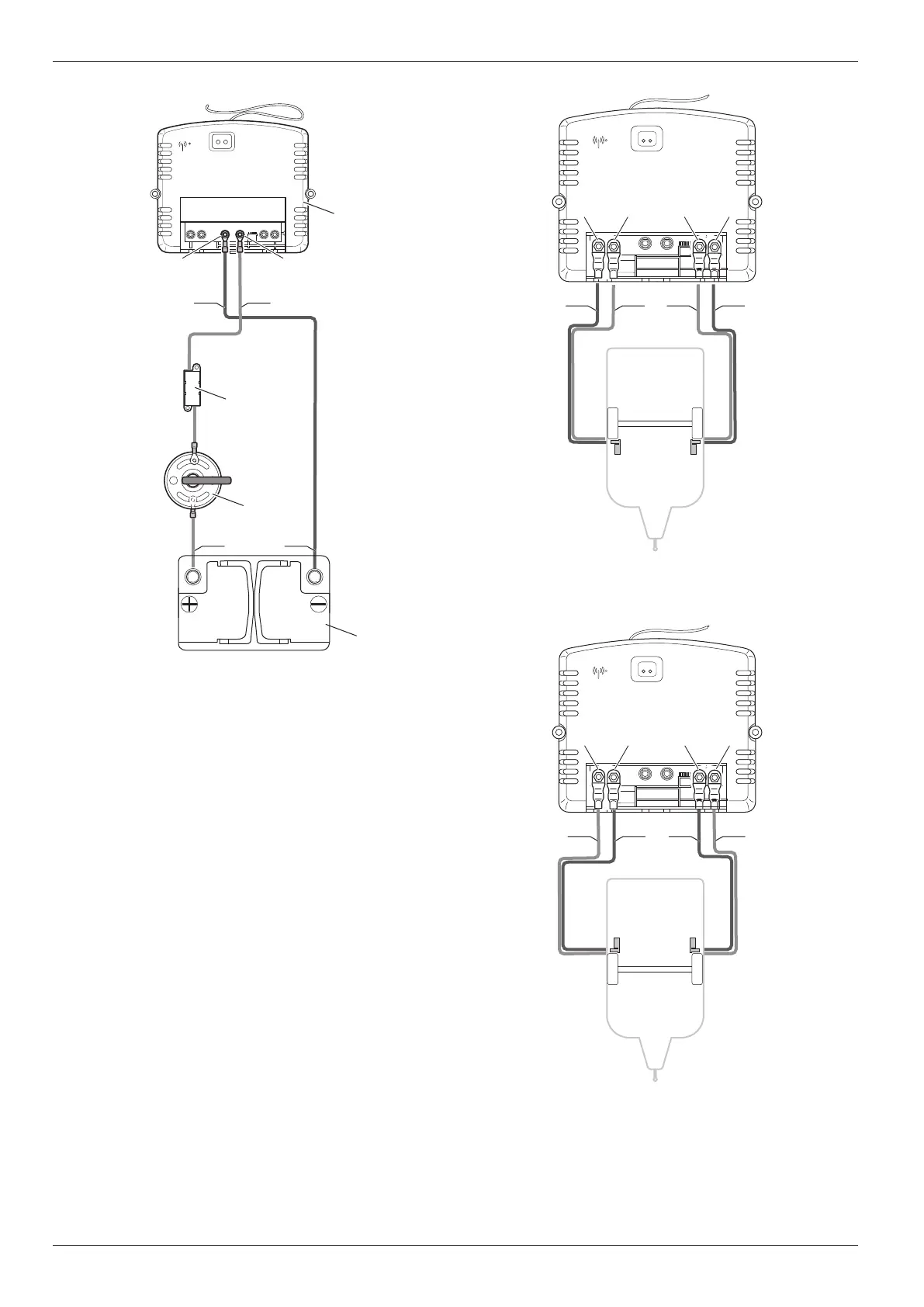
Once the cables have been routed out of the control
unit, they must be strain-relieved�
The motor cables must be routed together in such a
way as to prevent them from being torn o or dam-
aged�
1
4
3
2
RDBK
RD BK
BATT+BATT-
Fig� 42
1 Control unit
2 Fuse
3 Battery cut-o switch
4 Battery
Drive motor connection diagram
Installation in front of the axle
Top view

Table of Contents

Questions and Answers:

Question and Answer IconNeed help?

Do you have a question about the Truma Mover smart M RS1 and is the answer not in the manual?

Truma Mover smart M RS1 Specifications

General IconGeneral
BrandTruma
ModelMover smart M RS1
CategoryAutomobile Accessories
LanguageEnglish

Related product manuals