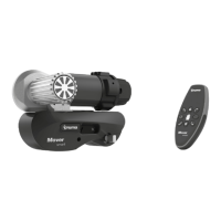
Mover smart M RS1Function check
32 EN
60040-00463 ∙ 00 ∙ 09/2023
DANGER
Personal injury due to a lack of safety pre-
cautions
If potential dangers, e�g� persons and objects in
the test area, are ignored prior to the function
test, this may lead to personal injury and proper-
ty damage�
There must be no persons or objects in the
test area�
Nobody may remain in or on the caravan�
WARNING
Malfunction of the manoeuvring system
due to failure to perform function test
Failure to perform a function test after installing
the manoeuvring system may lead to unforesee-
able malfunctions of the manoeuvring system�
Test all manoeuvring system functions after
installation�
If it is necessary to replace the remote control or control
unit (e�g� in case of loss), the remote control and control
unit must be re-paired with each other�
Pair the remote control and control unit in accord-
ance with the operating instructions�
•
To operate the manoeuvring system, the battery
must be fully charged�
•
There must be no obstacles around the caravan�
•
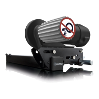
The drive rollers must not be engaged and the cor-
ner jacks must be raised�
Position the caravan on open, level ground and
apply the parking brake, or secure it with chocks to
prevent it from rolling away�
Connect the battery terminals to the battery�
Check all cables� The cables must be securely
fastened and must not be allowed to heat up� There
must be no indications of a short circuit, etc�
Switch on the remote control�
The functionality of the remote control is described
in the operating instructions�
If the green LED does not light up on the remote
control:
Check the polarity and condition of the batteries in
the remote control�
The remote control switches itself o after about
3minutes if no buttons are pressed�
If available: Establish the power supply for the ma-
noeuvring system using the battery cut-o switch�
Check that the drive motors are stationary�
With the remote control switched on, press the
FORWARD button� All the drive rollers must
now rotate forwards�
Engage the drive rollers on the tyres using the en-
gagement lever provided�
Release the parking brake or remove the chocks and
switch the remote control on again if it is switched
o�
Now check all functions several times in accordance
with the operating instructions�
6.4 Connecting the battery
NOTICE
Destruction of the electronics due to incor-
rect polarity
If the poles are reversed when connecting the
control unit to the battery, this can damage the
electronics�
Connect the battery connection cables to the
existing battery terminals� Connect the red
cable to the positive terminal and the black
cable to the negative terminal� Notice: Bat-
tery poles have dierent diameters�
When connecting the battery, observe the following:
•
Liquid electrolyte batteries must be installed in a
separate box with ventilation leading to the outside�
The fuse in the positive cable must be connected
outside the box� A separate box is not required for
gel or AGM batteries� Pay attention to the battery
manufacturer’s installation regulations�
•
The battery connector cables must not be extended�
The battery connector cables must be routed sepa-
rately from the motor cables, and must not run over
the control unit�
•
The battery must be positioned at least 40cm away
from the control unit�
•
Route battery connector cables so that they do not
chafe (particularly at lead-throughs through metal
panels)� Use suitable protection pipes to prevent
damage to cables� Connect the battery connection
cables to the existing battery terminals (red = posi-
tive, black = negative)�
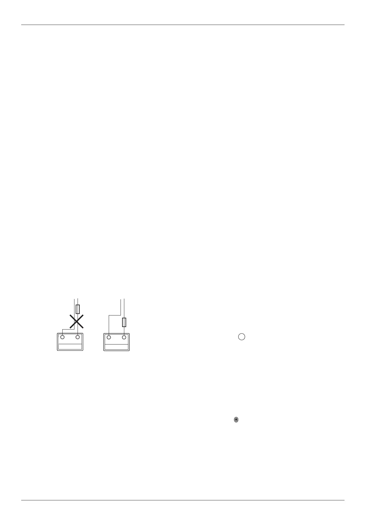
•
The two cables to the positive terminal and negative
terminal must be routed with a gap between them
until after the fuse in the positive cable�
+
-
+
-
Fig� 52
Connect the fuse in the positive cable near the posi-
tive terminal�
Route the battery connection cables to the control
unit and secure them using the cable clamps and
screws provided�
7 Function check
See operating instructions for notes on operation�
 Loading...