28 OVEN SYSTEMS
NOTE: The terminals with the orange wire always go
to Terminal
3 on US models.
To verify correct wiring (International), measure the
voltage between the taps on FT1 and FT2. The
voltage must be 220 VAC (Latin America), 200 VAC
(Japan), or 230 VAC (International).
High-Voltage Transformers
The high-voltage transformers are of ferro-resonant
design, which limits fault currents and minimizes
magnetron power changes due to input voltage
changes. The high-voltage transformer supplies the
high voltage for the voltage doubler circuit. They are
controlled via the K2 relay.
Wiring the High-Voltage Transformers
DANGER: Never attempt to touch, contact, or
measure the secondary voltage values of the
high-voltage transformers while they are
enabled. Lethal voltage will be present.
The proper reinstallation of a high-voltage transformer
is critical. Upon removing a high-voltage transformer,
make sure to note where each wire was installed. See
the oven schematic on page 49 for the wiring detail.
As shown in the schematic, transformers are installed
mirror opposite and wired
180
º
out-of-phase. It is
essential for longevity that the high-voltage trans-
formers remain 180
º
out-of-phase. This can be checked
by placing a volt meter across terminals
T1-1 and T2-1
(primary voltage)
.
With the microwave system energized, the volt meter
will read
the incoming voltage (different readings for
different electrical installations).
If the meter reads 0
VAC
, the high-voltage transformers are most likely
wired in-phase. As a last check, energize the microwave
system and verify the voltages between the taps on
each high-voltage transformer.
The wiring issue must be corrected prior to returning
the oven to service, as the voltages must be:
-
NORTH AMERICA: 208 VAC between 1&2and
240 between 1&3.
- LATIN AMERICA: 220 VAC
- JAPAN: 200 VAC
- INTERNATIONAL: 230 VAC
NOTE: The terminals with the orange dot/orange wire
always go to terminal
3 on US models.
Testing a Filament or HV Transformer
DANGER: Never attempt to measure the
secondary voltage values of the transformers
when they are connected to the magnetron
circuit. Lethal voltage will be present.
1. Disconnect the AC power source.
2. Remove the top cover of the oven and discharge
the high-voltage capacitors.
3. Disconnect all the wires in question going to the
transformer.
4. Use an ohmmeter to check the impedance of the
primary and secondary winding. Refer to the adja-
cent resistance table to determine if the transformer
is OK. If the resistance is different than the table
indicates, replace the transformer.
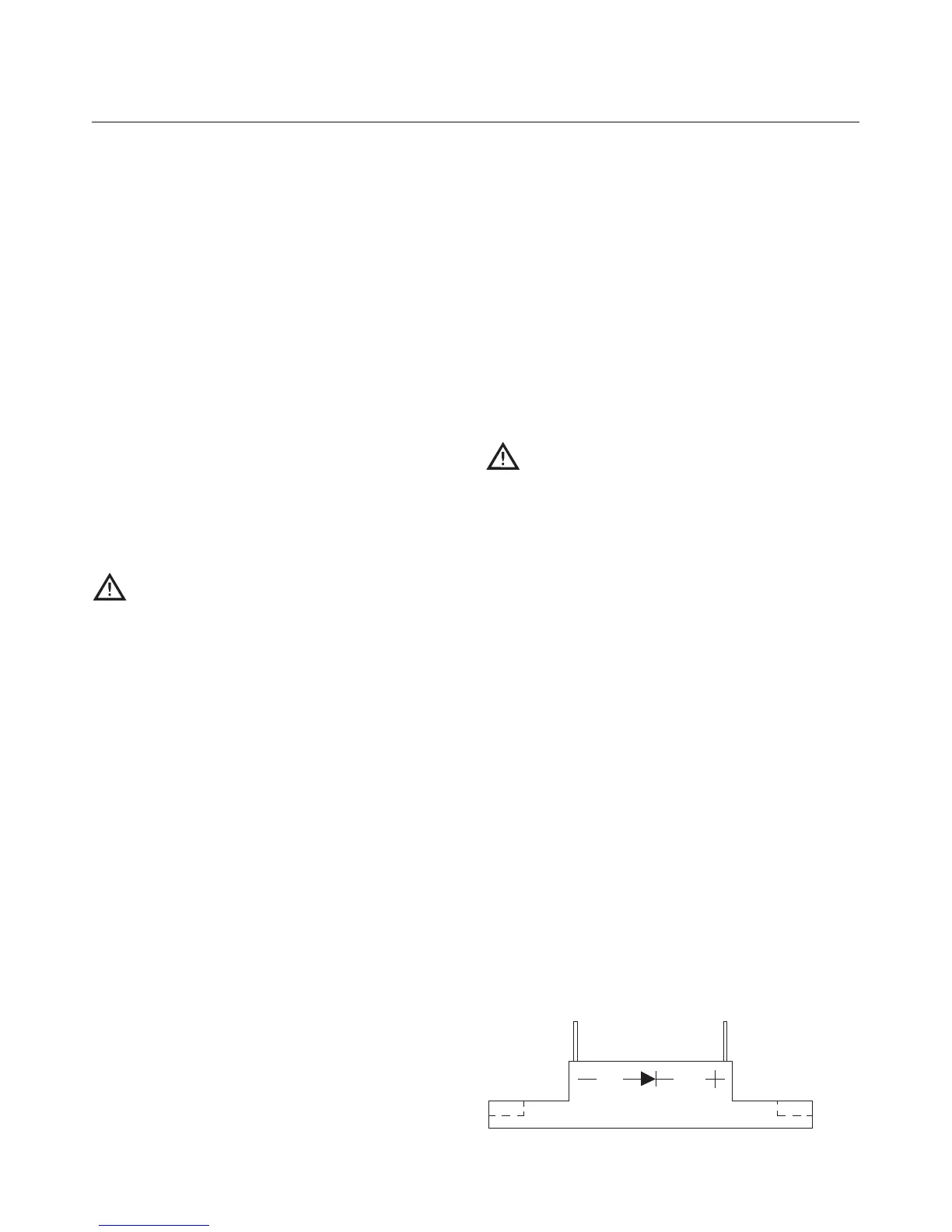
High-Voltage Diodes
The high-voltage diode (Figure 34) is assembled by
connecting several 1000-1500 volt semi-conductor
diodes in a series to increase the reverse voltage
capability. In the circuit, the high-voltage diode
conducts to prevent the filament voltage from
becoming positive, thus as the high-voltage winding
of the transformer goes to a peak of 2400 volts, the
high-voltage capacitor is charged to 2400 volts.
Figure 34: High Voltage Diode