30 OVEN SYSTEMS
Magnetrons
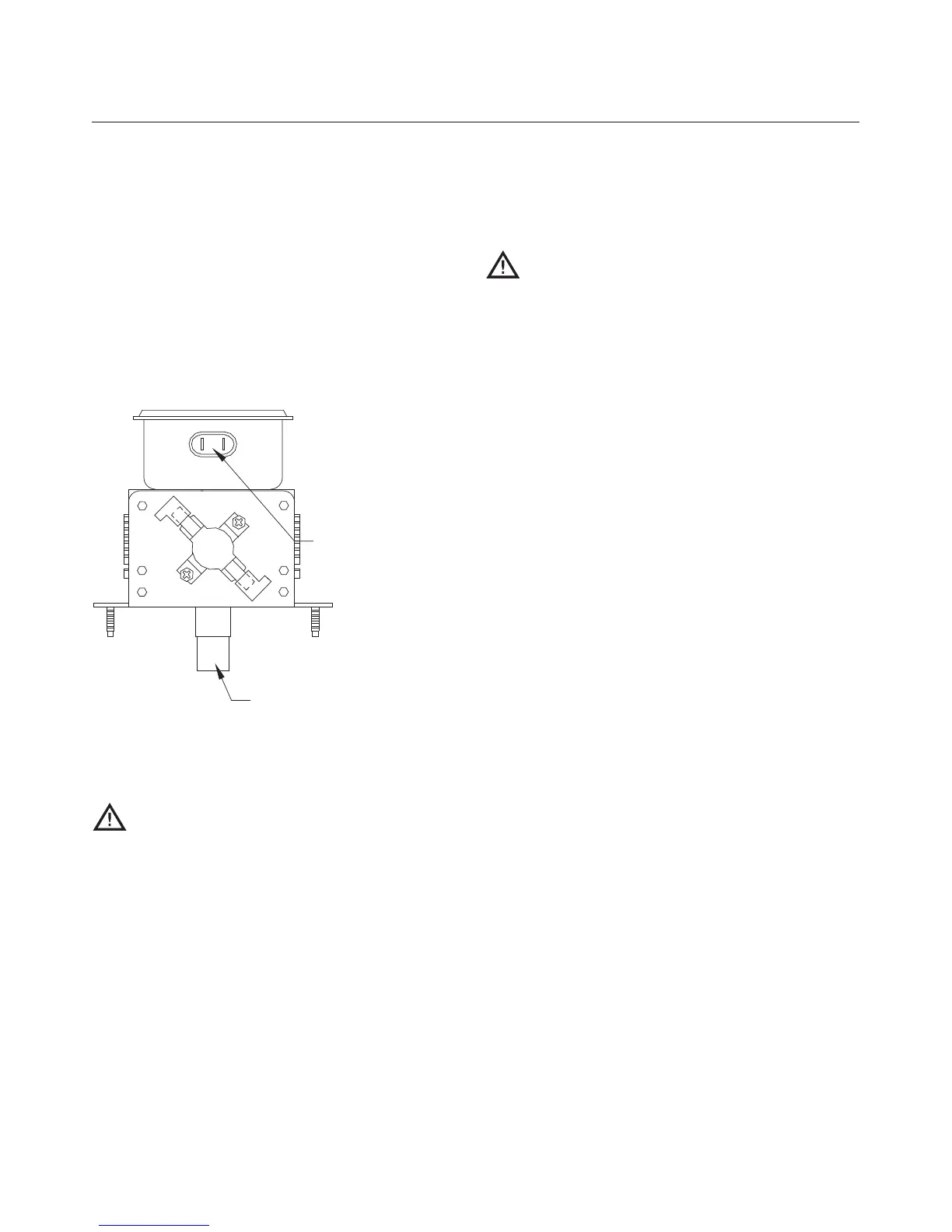
Figure 35. Magnetrons supply the RF energy at 2.45
GHz and begin to oscillate when they are supplied
with approximately 4.1 kVDC at approximately .350
mA. During operation, each magnetron will output a
nominal 1 kW of power.
If replacement is required, conduct a microwave
leakage test (pages 25-26) after installing a new
magnetron.
Testing a Magnetron for an Open/Shorted
Filament
DANGER: The only safe way to test a
magnetron is by a resistance test of its
filament. Never attempt to measure the
magnetron using any other method while the
microwave system is on. Death or serious
injury could occur.
1. Disconnect the AC power source.
2. Remove the top cover of the oven and discharge the
high-voltage capacitors.
3. Isolate the magnetron from the circuit by
removing the wires from the F and FA terminals.
Figure 35.
4. An ohmmeter connected between the filament ter-
minals (F, FA) should indicate a reading of less than
1 ohm. Figure 35.
5. A continuity check between either filament terminal
and the magnetron chassis should indicate an
infinite resistance (open).
CAUTION: Be careful to not allow debris
into the waveguides when servicing the
magnetrons.
Stirrer Motor and Assembly
The stirrer is responsible for evenly distributing hot air
and microwaves that are launched from the top of the
oven into the cook cavity. The stirrer is driven by a
motor that remains on during a cook cycle or when
the oven is in
TEST MODE. The stirrer motor turns off
when the cook cavity temperature recedes below 150°F
(66°C).
The i3 utilizes two versions of the stirrer and the
stirrer shaft. Ovens with serial numbers between 00001
and 01000 use a mica stirrer, whereas ovens with a
serial number of 01001 or greater use a metal stirrer.
Each stirrer type also has a unique shaft. For details
including part numbers and illustrations, see pages A-2
through A-3 and A-6 through A-7 of the appendix.
The stirrer motor can be tested in
TEST MODE (see
page 16).
Waveguides
The waveguides channel microwaves into the cook cav-
ity. If debris or contamination gets into the wave-
guides, the life of the magnetrons may be shortened.
Be careful to not allow debris into the waveguides
when servicing the magnetrons.
Microwave System Troubleshooting
The following faults may occur in relation to the
microwave system:
- F3: Magnetron Current Low (see page 39)
- F5: Magnetron Over Temperature (see page 40)
The following issues may occur in relation to the
microwave system:
- Electrical component failure (blank or
scrambled display, damaged control board, etc.)
- Food not cooking properly (see page 45)