APPENDIX - REPLACING OVEN COMPONENTS
A-11
Figure
Reference #
Item Description Item Part Number Hardware Description Hardware Part Number(s)
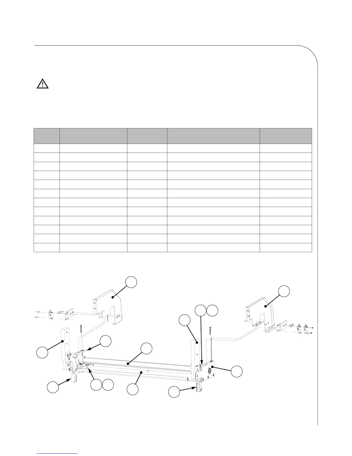
1 Hinge, Bracket, Slide, LHS i5-9196 Nut, Keps, Hex, #8-32, Ext Tooth, Cres 102962 (qty 4)
2 Hinge, Bracket, Slide, RHS i5-9195 Nut, Keps, Hex, #8-32, Ext Tooth, Cres 102962 (qty 4)
3 Hinge, Cam, Weldment, LHS i5-9313 Washer, Nylon, Hingepin C0504 (qty 1)
4 Hinge, Cam, Weldment, RHS i5-9314 Washer, Nylon, Hingepin C0504 (qty 1)
5 Hinge, Guide Block, Top i5-9394 Nut, Keps, Hex, #8-32, Ext Tooth, Cres 102962 (qty 4)
6 Hinge, Guide Block, Bottom i5-9393 None None
7 Hinge, Gusset, LHS i5-9178 Nut, 1/4 - 20, Serr, Hex Flange, Plated Steel 100906 (qty 2)
8 Hinge, Gusset, RHS i5-9179 Nut, 1/4 - 20, Serr, Hex Flange, Plated Steel 100906 (qty 2)
9 Hinge Module, Base i3-9193 None None
10 Hinge, Torsion Bar i3-9144 Spacer, Adjustment Call TurboChef
11 Hinge, Weldmt, Ctrblnce Brkt, LHS i5-9326 Screw, 10-32 x 3/8 lg, PFLH, 100 Deg, SS 101401 (qty 3)
12 Hinge, Weldmt, Ctrblnce Brkt, RHS i5-9327 Screw, 10-32 x 3/8 lg, PFLH, 100 Deg, SS 101401 (qty 3)
Removing Right and Left Covers Required (Figure A-10)
CAUTION: Before removing/installing any component, make sure the oven has cooled and the
screen reads “Oven Off.”
Hardware listed is required for installing component to oven.
10
3
4
1
2
7
8
12
9
11
5
6
Figure A-10: Counter Balance Assembly, Hinge, and Switch Detail
5
6
 Loading...