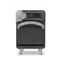
24 OVEN SYSTEMS
Interlock Switches
The primary, secondary, and monitor interlock
switches engage and disengage in sequence to ensure
a proper seal. When the door is opened, the switch
sequence is P, S, M. Subsequently, the sequence is
M, S, P when the door is closed.
Adjusting the Door Switches
Proper door switch sequence is critical. The safety
interlock system is designed to disable the microwave
circuit (blow F3 fuse) if the monitor door switch
opens before the primary or secondary switches
during microwave operation. Verifying the door
switchs equence is highly recommended when
servicing an oven with a blown F3 fuse.
WARNING: This procedure requires work while
the oven is hot. To avoid burns, be careful when
adjusting the door switches.
1. Ensure the oven door is closed.
2. Verify the oven door is adjusted properly and
the oven is at operating temperature before
attempting to adjust the door switches. If the
oven has multiple set temperatures, use the
highest temperature. If a door adjustment is
required, refer to pages 22 and 23 for details.
3. If an open door switch is not allowing the oven
to preheat, remove the side panels and loosen and
move both the left and right door switch brackets
to close the switches.
NOTE: Step 3 is not a completed repair. Proper
switch operation must be confirmed before putting
the oven into service; continue to step 4.
4. With the oven at operating temperature, enter
TEST MODE (page 16) to view the status
indicators of the primary, secondary, and
monitor door switches.
5. Adjust the position of the door switches/
brackets to ensure the proper sequence.
NOTE: Opening the door must show the sequence as
P, S, M. Closing the door must show the opposite
sequence M, S, P. After final adjustments, retighten
the hex bolts and confirm the brackets are secure.
6. Reinstall the side panels.
7. Perform a MW leakage test (page 25)
Hinges and Counter-Balance Assembly
The door hinges and counter-balance assembly ensure
the door consistently opens and closes smoothly. The
counter-balance assembly also allows the door to
remain open at convenient positions; i.e., partially
open, fully open.
Adjusting the Counter-Balance Assembly
Adjustments either increase or decrease the amount of
counter-pressure being applied to the door.
WARNING: This procedure requires work while
the oven is hot. To avoid burns, be careful when
adjusting the counter-balance assembly.
NOTE: In Figure 32, some oven components have
been removed for clarity. The adjustment procedure
must be performed with the counter-balance and
hinges installed to the oven chassis.
1. Heat the oven to operating temperature.
2. Ensure the door is adjusted properly and closed.
Refer to page 22 “Adjusting the Oven Door.”
3. Remove both side panels.
4. Remove both left and right side door switch
assemblies for access to the adjustment area.
5. Remove the last gusset screws (closest to the
switch assemblies) for tool access.
6. Use adjustment tool P/N i5-9387 to check the
distance between the bracket and counter-
balance assembly (see Figure 32).
7. Insert the adjustment tool and use a 3/32”
hex wrench to tighten the adjustment screw
against the bracket so the tool cannot slide out.
8. Turn the adjustment screw two complete
revolutions counter-clockwise to achieve the
proper tension and remove the tool.
9. Repeat steps 5-8 for the other side.
10. Reinstall the gusset screws and tighten.
11. Reinstall the door switch assemblies, verifying
the switches are in the closed position (i.e.,
snug against the actuator).
12. Warm up the oven, allowing the additional 8
minute “soak” to achieve thermal equilibrium
in the cook cavity.
13. Adjust the door switches to ensure the proper
opening and closing sequence (details adjacent).
14. Reinstall all components and side panels.
15. Test for microwave leakage before returning the
oven into service (page 25).