A-10
APPENDIX - REPLACING OVEN COMPONENTS
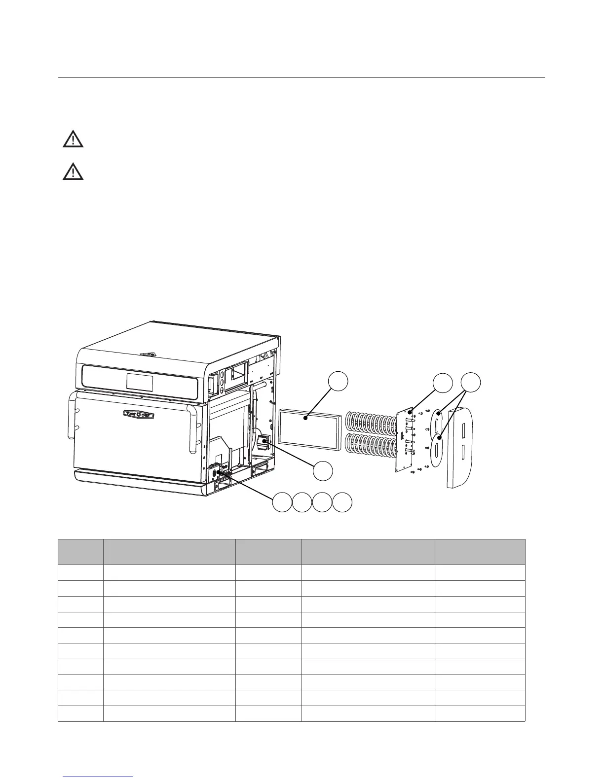
Figure A-9: Removing Right Side Cover Required
Figure
Reference #
Item Description Item Part Number Hardware Description Hardware Part Number(s)
1 Catalytic Converter i3-9066 None None
N/A Cover, Right Side i3-9302 Screw, #8, Serr PPHD, Truss, Black Oxide 101691 (qty 5)
2 Heater Assembly i3-9380 Screw, Sh Mtl #8 x 1/2, Serrated PHTRH 101688 (qty 10)
3 Helper Spring, Interlock Switch* i5-9397 None None
4 Interlock Switch - Monitor* 102012 Screw, #4-40 x 1”, PPH, Sems 102903 (qty 2)
5 Interlock Switch - Secondary* 102012 Screw, #4-40 x 1”, PPH, Sems 102903 (qty 2)
6 Mounting Bracket, Interlock Switch* i5-9272 Screw, #10-32 x 3/4 lg, PPH Sems, Int Th 102937 (qty 2)
N/A RTD, Cook Cavity HHC-6517-2 Screw, Sh Mtl #8 x 1/2, Serrated PHTRH 101688 (qty 2)
7 Shield, Heater Insulation (x2) i5-9216 None None
8 Thermostat, High-Limit 102075 Screw, M4 x 6, PPH SQ CO Sems, Zinc 101672 (qty 2)
Removing Right Side Cover Required (Figure A-9)
CAUTION: Before removing/installing any component, make sure it is disconnected from the
wire harness (where applicable).
CAUTION: Be careful to not tear the insulation when servicing components. Always reset the
insulation properly before reinstalling the side panel.
Hardware listed is required for installing component to oven.
To remove the right side cover:
1. Remove the screws securing the panel to the oven frame.
2. Remove the right side cover.
* NOTE: For more interlock switch detail, see Figure A-10, page A-11.
1
2
4
5
6
7
8
3
 Loading...