OVEN SYSTEMS
45
NOTE: Do not push one end at a time, which
could cause the opposite end to lift away from
the flange.
3. Re-tighten the hex screws.
4. Pull the door open only 0.25” (6 mm) and let go
of the handle.
The door must completely snap shut on its own. If the
door sticks and force is needed to finish closing it, it is
out of adjustment.
WARNING: Perform a microwave leakage test
(page 46) after adjusting the oven door.
Interlock Switches
The primary, secondary, and monitor interlock
switches engage and disengage in sequence to ensure
a proper seal. When the door is opened, the switch
sequence is P, S, M. Subsequently, the sequence is M,
S, P when the door is closed.
Adjusting the Primary, Secondary, and
Monitor Switches
WARNING: This procedure is performed while
the oven is hot. To avoid burns, be careful
when adjusting the switches.
Use the following procedure to adjust the primary,
secondary, and monitor switches. The secondary
switch is located on the left side hinge assembly
and the monitor switch is located on the right side
hinge assembly. The primary switch is located on the
upper-left corner of the oven and utilizes an actuator
(attached to the door) and toggle assembly (attached
to the chassis) to engage (Figure 33). See page A-8 of
the Appendix for switch assembly detail.
1. Ensure the oven has been at operating temperature
for at least fifteen minutes.
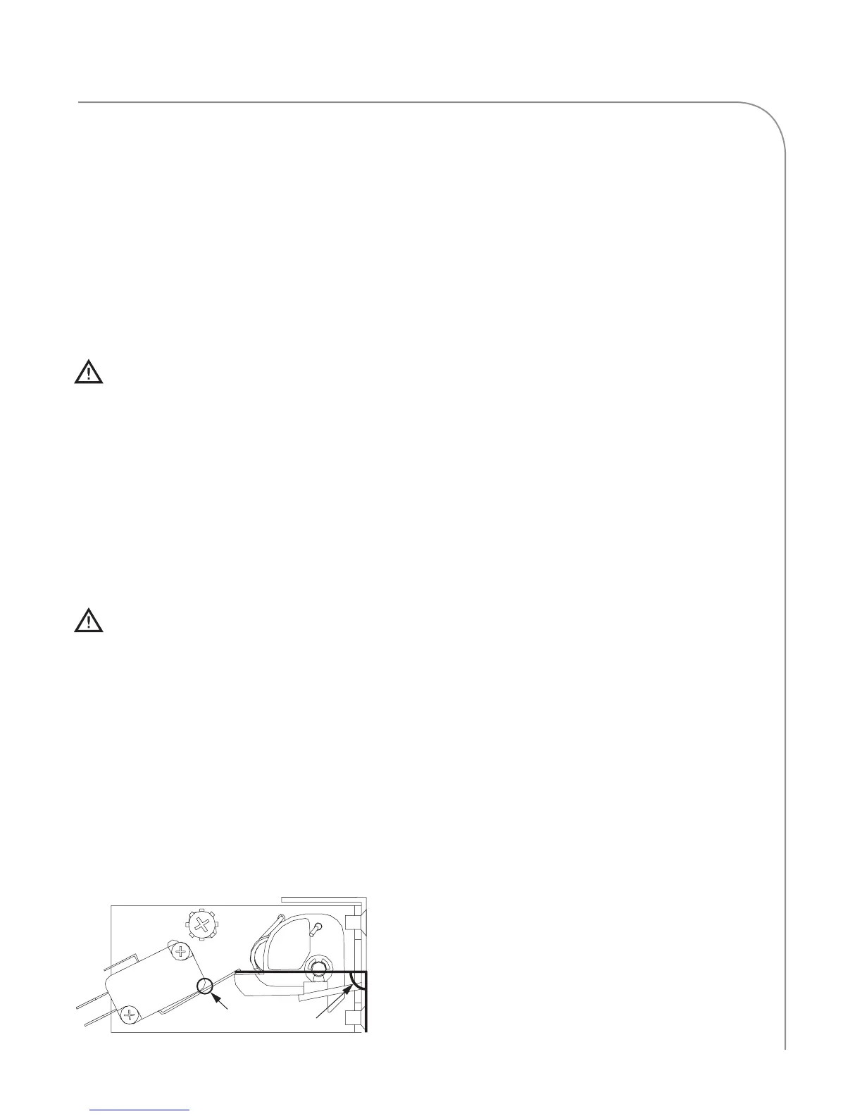
2. If adjusting the primary switch, confirm the
primary switch’s latch toggle is in the correct
position.
a. Visually inspect the latch toggle position and
verify it is angled at no less than 85° and no more
than 90° in reference to the front flange (oven
face). See Figure 33.
b. If the toggle is less than 85° or greater than 90°,
correct the toggle’s position by installing a
spacer/shim (the more distance from the flange,
the less angle on the toggle):
- NGC-1169-1: Shim, 0.030” (0.762 mm)
- NGC-1169-2: Shim, 0.045” (1.143 mm)
c. Verify the position of the toggle by opening and
closing the oven door several times.
3. Adjust the switch(es):
a. Enter Test Mode (page 14, 29 for Touch).
b. Open the oven door and verify P, S, and M
disengage in sequence.
c. Close the oven door and verify M, S, and P
engage in sequence.
d. If the switches do not engage or disengage in
sequence, close the door and adjust the
necessary switch(es) by loosening the two #4-40
screws and #8-32 screw until the proper
sequence is achieved.
NOTE: DO NOT allow the switch paddle to rest
on the body of the switch in the closed door posi-
tion. The final adjustment requires a minimum of
a 0.030” (0.762 mm) gap to avoid over-travel and
bent/damaged switches.
4. Open and close the door several times to verify
the switch gap.
5. Energize the microwave system and open the
oven door.
6. Verify the W indicator is backlit, meaning the
microwave system turns off when the door is
open.
7. Perform a microwave leakage test (page 46).
Figure 33: Primary Switch Adjustment
0.030” (0.762 mm) Gap
85° - 90° angle

 Loading...