APPENDIX REPLACING OVEN COMPONENTSA-12
Figure
Reference #
Item Description Item Part Number Fastener Description
Fastener Part
Number(s)
1 Capacitor, High-Voltage (x2)
100216 (Japan 50 Hz)
ENC-3010-2 (Japan 60 Hz)
ENC-3010-1 (All others)
Screw, #6-32 x 3/8, Int Tooth, PPH, SS
Nut, #6-32 Keps, Ext Tooth, SS
102911
102961
2 Capacitor Clamp (x2)
104197 (Japan 60 Hz)
100134 (All others)
Screw, #8 x 1/2, Serr Ph Truss Hd, Sheet Mtl 101688 (qty 2)
3 Diode, High-Voltage (x2) 100481 Screw, #8 x 1/2, Serr Ph Truss Hd, Sheet Mtl 101688 (qty 2)
4 Duct, Magnetron Cooling Fan, L* i1-9479 Screw, #8 x 1/2, Serr Ph Truss Hd, Sheet Mtl 101688 (qty 2)
5 Duct, Magnetron Cooling Fan, R* i1-9480 Screw, #8 x 1/2, Serr Ph Truss Hd, Sheet Mtl 101688 (qty 2)
6 Jumper, Capacitor (Intl 50 Hz only) i5-9378 None None
7 Magnetron (x2) NGC-3015 Screw, #8 x 1/2, Serr Ph Truss Hd, Sheet Mtl 101688 (qty 4)
8 Power Cord Contact factory None None
9 Terminal Block
102049 (1 Ph)
102043 (3 Ph)
Screw, #10-32 x 3/4 Lg, PPH Sems, Int Tooth 102937 (qty 2)
10 Thermostat, Magnetron, 270°F (x2) 104228 Screw, Sh Mtl, Drill Point, 6-32 x 3/8, PPHD, Zinc 101684 (qty 2)
11 Transformer, Filament (x2)
NGC-3061-1 (USA)
NGC-3061-2 (Intl)
NGC-3061-3 (Japan)
Screw, #8 x 1/2, Serr Ph Truss Hd, Sheet Mtl 101688 (qty 4)
12 Transformer, High-Voltage (x2)
NGC-3062-1 (USA)
NGC-3062-2 (Intl)
NGC-3062-3 (Japan)
Screw, #8 x 1/2, Serr Ph Truss Hd, Sheet Mtl 101688 (qty 4)
13
Wire Harness, Line Voltage
(not shown)
i1-9172 (1 Ph)
i1-9171 (3 Ph)
None None
14
Wire Harness, Cooling Fans
(not shown)
i1-9174 None None
15
Wire Harness, Heaters
(not shown)
i1-9239 None None
16
Wire Harness, Transformers
(not shown)
i1-9173 None None
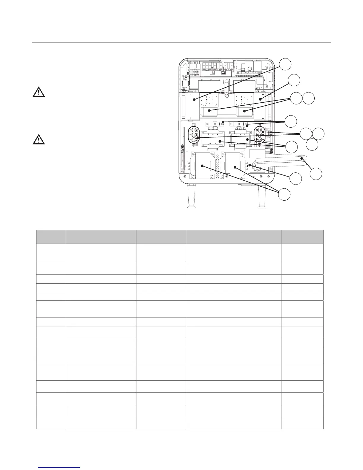
Replacing Items - Removing Outer
Shell and Back Cover Required
(Figure A-18)
DANGER: Before replacing any oven
component, ensure the oven is removed
from any power source. Replacing a
component while the oven is plugged
in can result in serious injury or death.
CAUTION: Be careful to not tear the
insulation when servicing components.
Always reinstall the insulation properly
before reinstalling the outer shell or
back cover.
NOTE: Fasteners listed are required for install-
ing component to oven.
Figure A-18: Outer Shell and Back Cover Removed
3
11
12
8
2
1
10
7
* NOTE: Left and right orientation based on looking at the back of the oven.
4
5
9
6

 Loading...