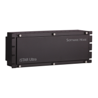
Overview
7–6 iSTAR Ultra Installation and Configuration Guide
Initial Configuration
Initial configuration of the IP-ACM can be performed in two modes: Normal Operation mode
and Standalone configuration mode.
The offline functionality of the IP-ACM allows the last 1,000 valid cards and/or a specific
personnel group of no more than 100.
Normal Operation Mode
1. Ensure the IP-ACM SW1-1 is OFF.
2. Apply the power using the PoE (J1) or the Local Power (P1) port.
3. Push the SW3 reset switch.
4. Connect the IP-ACM board to the Ethernet port directly on a DHCP network and run the iSTAR
Configuration Utility (ICU), 6.4.0 or later, on the same subnet using an Ethernet cable.
5. Ensure you have previously configured the iSTAR Ultra controller in order to obtain the iSTAR IP
address for the IP-ACM configuration.
6. To discover the IP-ACM, click the IP-ACM icon in the ICU. A list of IP-ACM modules appear.
7. Right-click the IP-ACM you want to configure and select Configure IP-ACM.
8. Enter the password: iSTAR, and click Login. The IP-ACM Configuration/Status web page appears.
9. In the Configuration section, enter the iSTAR IP address assigned to the iSTAR Ultra controller.
10. Click Save and then click Reset.
Standalone Configuration Mode
1. If there is no DHCP network, or the installer prefers configuring the IP-ACM before putting it on the
network, switch SW1-1 to ON.
2. Apply power using the PoE (J1) or the Local Power (P1) port.
3. Push the SW3 reset switch.
4. The IP-ACM will start with a static IP address of: 192.168.1.111.
5. Connect a laptop or PC, statically configured in the 192.168.1.0/24 subnet, directly to the IP-ACM
via an Ethernet cable.
6. Launch a browser and open a web page to 192.168.1.111.
3.To comply with UL requirements, use shielded, minimum 22 AWG stranded, twisted pair cable for monitor points,
DSMs, and REXs. Use Belden 9462 or equivalent.
4.It is important to note that the aggregate load of each pair of RS-485 and Wiegand connections together must not exceed
750mA. Each set of RS-485 and Wiegand can support 750mA. Maximum combined output limit for readers and locks is
23W.
5.Voltage depends on selection of power feed (L1 or L2). Maximum combined output limit for readers and locks is 23W.
6.Compliance with IEEE 802.3 (AT or AF) specifications was not verified as part of UL294/B.
7.Maximum combined output limit for readers and locks is 23W.
NOTE
The MAC Address of the IP-ACM is located on the board.

 Loading...