General Control Module
5–6 iSTAR Ultra Installation and Configuration Guide
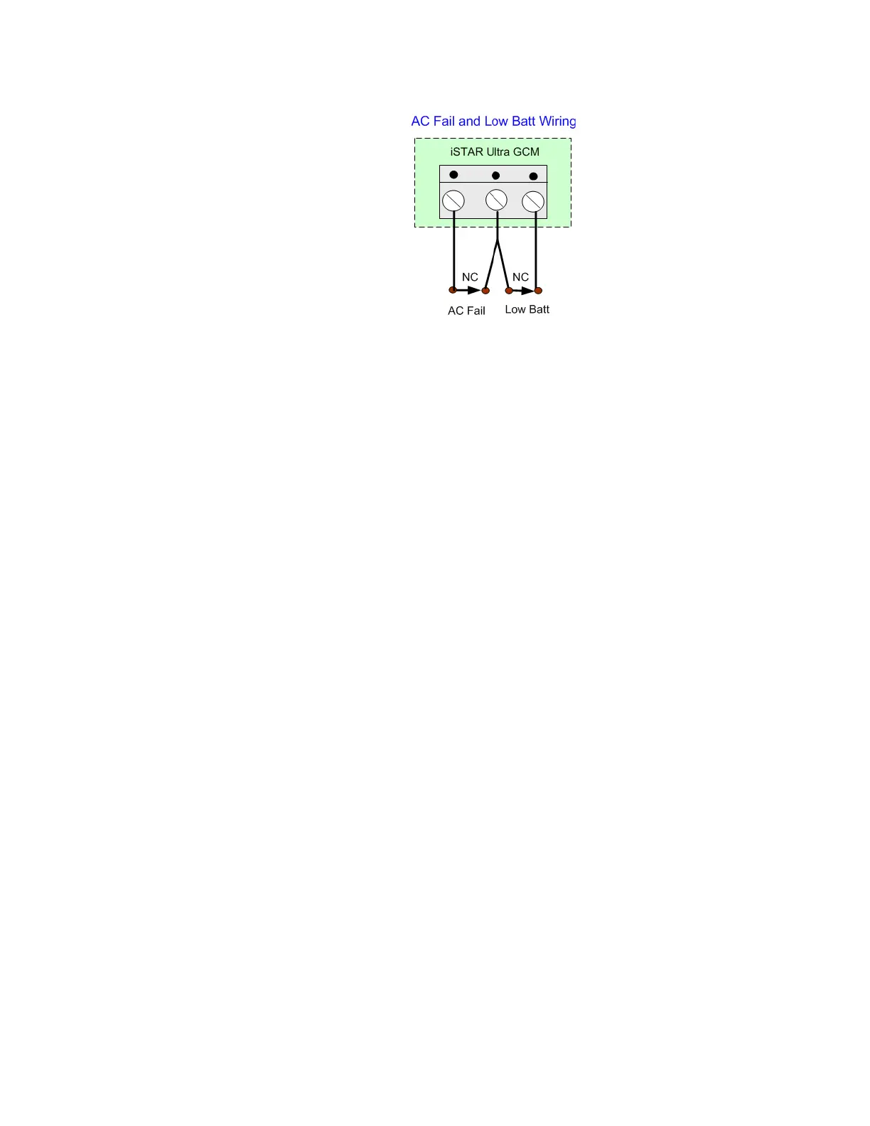
AC Fail Input
Indicates whether the external power source has reported loss of its main power.
Shares the connector and Ground pin with Low Battery.
Normally closed dry relay contacts are required. This signal is normally wired to the
energized NO (Normally Open) output on the apS.
Configurable on the host as an unsupervised input.
Low Battery Input
Indicates whether the external power source has reported its battery as low.
Wired in from external power source.
Shares the connector and Ground pin with AC Fail.
Normally closed dry relay contacts are required.
Configured on the host as unsupervised input.
Tamper - J1
Figure 5-2 on page 5-6 shows Tamper - J1 NC (Normally Closed). It is connected to the Tamper
switch on the enclosure. If there is no standard enclosure, be sure that there is a jumper across
the two pins.
In a standard wall enclosure, the GCM and ACMs have a Tamper Input. The Tamper switch
can be only be connected to the GCM. Remove the two configurations in C•CURE 9000 for the
ACMs. Alternatively, short the two pins on the unused ACM Tamper Inputs, since it is an NC
connection.
Figure 5-2: Tamper -J1