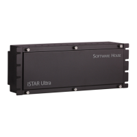
General Control Module
iSTAR Ultra Installation and Configuration Guide 5–7
The tamper switch controls many LEDs, to preserve power and also turns off the super bright
LED when the door is open. When the door is opened the small power LEDs are on. The LCD
is also off when the door is closed.
GCM Power - J4
12 Vdc @ 4.5 Amps max (Note: pin 1 on the left is +12 Vdc, pin 2 is GND.)
RS-485 1 and 2 (J12 and J13)
Used for Aperio Hubs and Schlage PIMs.
Each Port can support up to fifteen Hubs. Each Hub can support either one Reader or eight
Readers.
USB Type A - J8 and J9
Four type A ports used to communicate with ACMs and to import encryption keys from a
Certificate Authority using a thumb flash drive.
USB Micro A-B - J7
Not currently used. Future option.
RS-232 Diagnostic Port (P4)
Software House Tech Support and Engineering use for troubleshooting.
COMM Board Connector - J15
Not supported. Future option.
NOTE
The Tamper, Low Battery, and AC power fail inputs must be enabled
and connected to report for compliance with UL requirements.
Shielded cable must be used for AC Fail and Low Battery Input
connections.

 Loading...