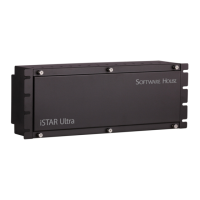
Access Control Module
iSTAR Ultra Installation and Configuration Guide 6–13
• Form C
Jumper for each relay to select Wet/Dry and Wet power source
It is convenient to configure a Door with all the components together in one of these sections,
but it is not a requirement. However, all door components must come from the same
controller.
Use the C•CURE Administration Workstation to configure the output as Normally Energized
for the Fail Safe case.
Dry Relay Wiring
Figure 6-11 on page 6-13 shows DRY relay wiring. Use NO or NC as appropriate. Notice that
jumper is in the Dry position.
Figure 6-11: Dry Relay Wiring
Wet Relay Wiring
Figure 6-12 on page 6-14 shows Wet wiring for a normal NO Latch. The iSTAR Ultra will
supply 0 to 30 Vdc, depending on the input supply. Current is limited to 0.75 A. Notice that the
GND is used for common, not the C pin. Notice that the jumper is in the Wet position.

 Loading...