9-8
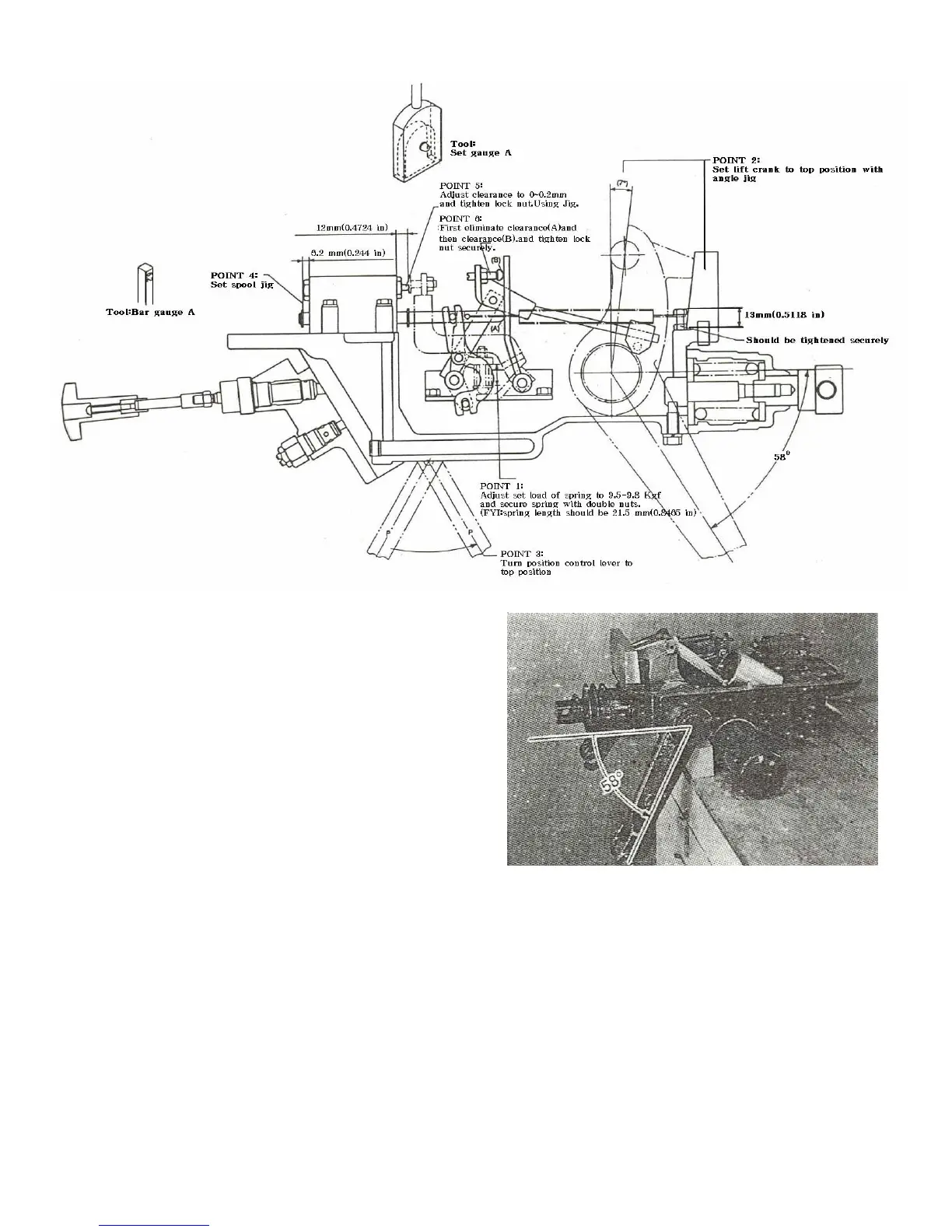
4. ADJUSTMENT OF THE LINK MECHANISM
Fig.9-11
1)Adjustment of the position-control
link mechanism.
Place the cylinder case assembly upside down
so that the lift arm can be moved freely.
Point 1.
Set the load of the pressure spring of the pilot
spool control arm to be 9.5-9.8 Kgf (20.9-21.6
lbs):the installed length of the spring is about
21.5 mm(0.847 in).
Note:
The cylinder should be removed ahead of time.
Point 2
Set the lift crank to the top position.Adjust the
top position using an angle setting tool or
determine the position where the angle of the
lift arm from horizontal is 58°
Point 3
Set the position control lever to the top position.
Point 4
Fix the clearance between the back face of the
snap ring on the main spool on the control valve
front and the casing to be 6.2 mm(0.2444 in) with
a setting tool,while the main spool is set in the
neutral position.

 Loading...