Doc No. FM0804 issue 4 Page 16
10. NETWORK TERMINATION BOARD
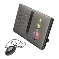
SYSTEM NETWORK
There are 3 blocks of pluggable XT2 network terminals - if there are more than 3 legs simply connect in parallel in any
block. The terminals on the system network have the following functions;
24V DC supply for network devices - fused at 1.6A
RS485 bi-directional data bus
Audio 1: intercom loudspeaker & microphone
Audio 2: intercom loudspeaker & microphone
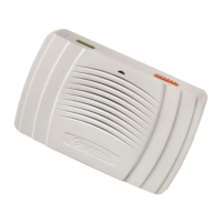
PA AMPLIFIER
The PA Amplifier(s) are connected to the Termination board. One PA amplifier can drive 80 intercoms, a second PA
Amplifier will be required on installations with more the 80 intercoms and the PA wiring must be split into 2 legs.
Enable signal to PA amplifier board
Audio to PA amplifier input
RS485 bi-directional data bus
PA audio (100V line) from PA amplifier 1
PA audio (100V line) from PA amplifier 2
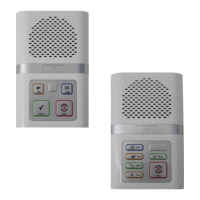
DOOR ENTRY NETWORK
The door entry panel(s) are connected to the Termination board;
24V DC supply door panel - fused at 1.6A
RS485 bi-directional data bus
Audio 1: door panel loudspeaker & microphone
Audio 2: door panel loudspeaker & microphone
Audio 1: telephone loudspeaker (C2) & microphone (C1)
Audio 2: telephone loudspeaker (C2) & microphone (C1)
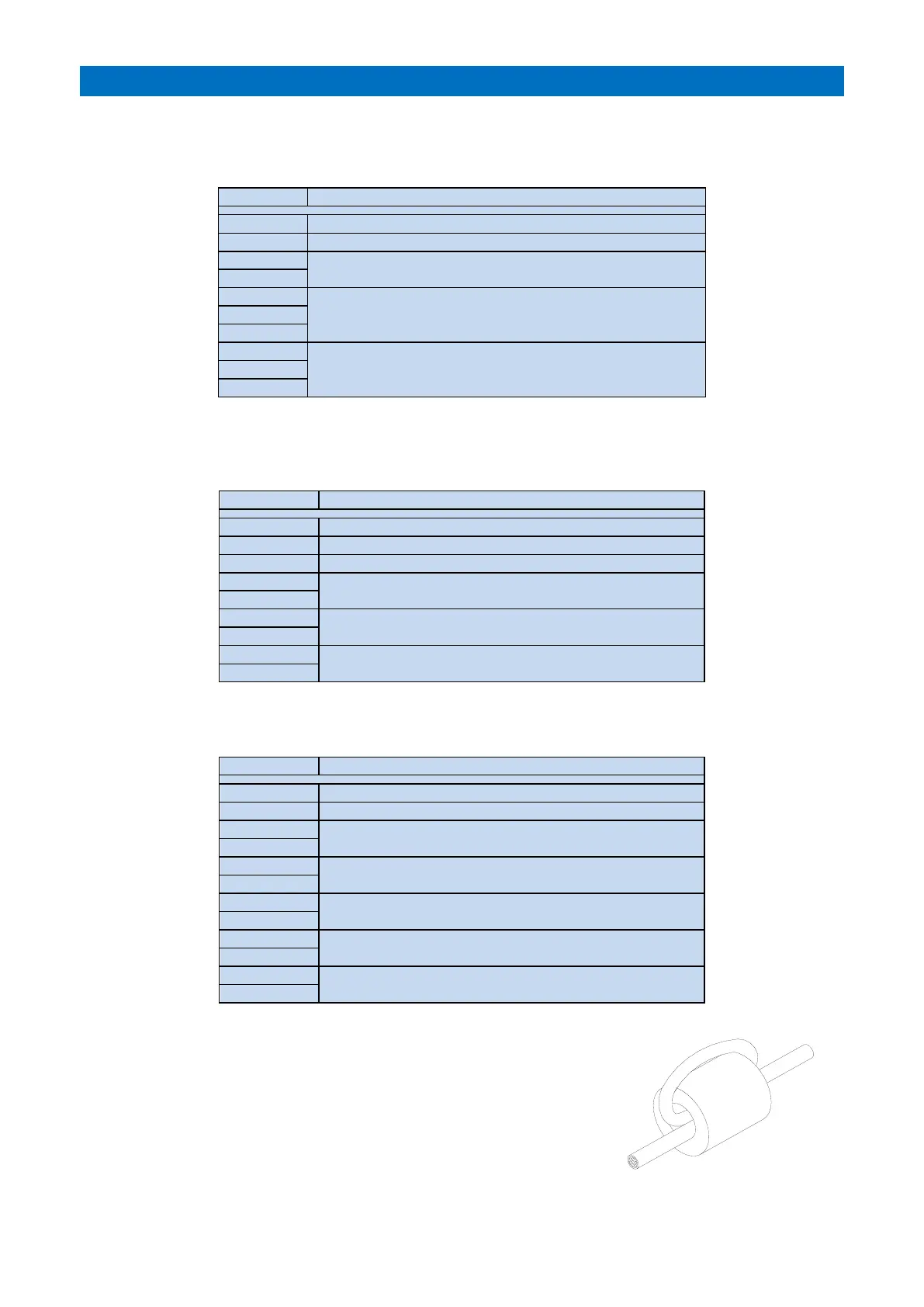
FERRITE CORE
Each leg of network wiring should be looped through a ferrite core before being
connected to the Termination board.
This will suppress any voltage transients induced on the Network wiring and
greatly reduce the likelihood of damage to the main CPU board.
Four ferrite cores are provided in the kit of parts with the Advent XT2 controller,
for additional ferrite cores order Tynetec P/No. T06050.