Doc No. FM0804 issue 4 Page 26
The input types shown are the
factory defaults.
The inputs can be changed per
intercom in programming - see the
Tenants Units Create/Edit section
of the Advent XT2 Programming
Manual (Doc No. FM0815).
Options DIL switch 1
in the intercom must
be ON when an I/O
Expander is
connected
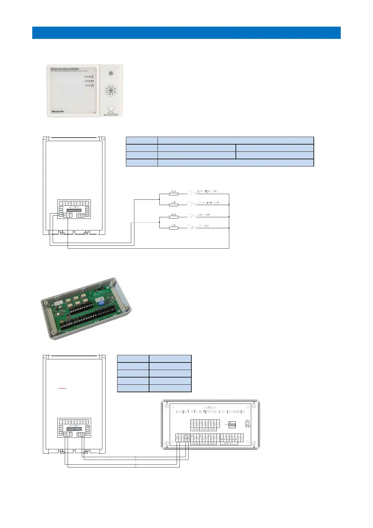
16. INTERCOM UNIT AUXILIARY DEVICES
4 ADDITIONAL INPUTS
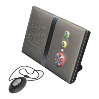
I/O EXPANDER UNIT
INPUT 1: 47K default low temp
INPUT 2: 18K default door exit
Common for all inputs 1-4
Up to 4 additional devices such as gas detectors or CO detectors etc. can
be connected into an intercom. They should be mains or battery powered
or be connected to a separate low voltage supply.
Additional devices must have a normally open clean contact output which
closes on alarm. Each input requires a 18K or 47K resistor connected in
series as shown below.
The 4 input types can be configured per intercom in system programming.
Advent XT2 I/O Expander Part No. ZXT925.
One I/O Expander can be connected per intercom to provide an
additional 6 N/O inputs and 6 changeover relay contact outputs.
Inputs are triggered by switching 0V through a normally open clean
contact.
Changeover clean contact relay outputs are rated at 30V DC 1A.
The 4 way DIL switch
(SW2) has no function.
The I/O Expander inputs/outputs must be setup
in programming - see the Tenants IO Unit
section of the Advent XT2 Programming
Manual (Doc No. FM0815).