31
shortest time possible and protect the safety of both personnel and the equipment.
To power on the robotic arm, the control box must be connected to the power supply.
In this process, the corresponding IEC C19 wire must be used.
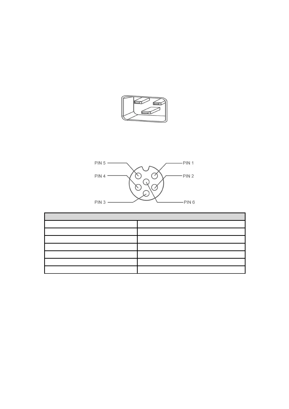
Connect to the standard IEC C20 plug of the Control Box to complete the process, see
the figure below.
2.1.3. Definition of the Robotic Arm Industrial Connector
6-Pin Industrial Connector (Robot Communication )
Industrial connector wire sequence
2.2. DC Control Box
2.2.1. External Interfaces of Control Box
Except that the DC Control Box is connected to different power sources, the other
electrical interface specifications and functions are the same as the AC Control Box.