YK11-0016-DI-002-08
54
5.6.1 Preparation
The separate exhaust port of the lubricating chamber is at the center of the oil trap flange (B) on the
top on the motor-side cover. It is covered with a plug to keep off foreign matter on delivery.
(1) Remove the plug from the separate exhaust port of the lubricating chamber.
(2) Arrange the piping to the separate exhaust port and the inlet port of the lubricating chamber.
CAUTION
The u
ltimate pressure of the pump for separate evacuation of the
lubricating chamber should be equivalent to that of the fore pump.
5.6.2 Water Piping, Electrical Connection and Lubrication.
Follow the procedure in the “3.2” , “3.5” , “3.6”.
5.6.3 Checking lubricating oil level
Follow the procedure in the “3.2” , “4.1” , “4.2”.
5.6.4 Oiling mechanical seal
Follow the procedure in the “3.2” , “4.1” , “4.2”.
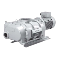
5.6.5 Pumping
(1) Close the inlet port either by closing the valve above the inlet side of the mechanical booster
pump or by providing a blind flange to the intake port.
(2) Run the pump for evacuating the lubricating chamber to evacuate the lubricating chamber
of the mechanical booster pump.
Then run the backing pump to evacuate the mechanical booster pump.
Here, make sure that the pressure at the inlet port or exhaust port of the mechanical booster
pump lowers to near the ultimate pressure of the backing pump (13 to 1.3 Pa with the
standard backing pump).
If the pressure does not lower, check the piping for leakage or the backing pump for defect.
Follow the procedure in the “4.1”, “4.2” Operation”.
5.6.6 Checking rotational direction
After completion of evacuation check the rotational direction.
Run the pump for approximately three second while looking through the viewing port.
If the gears rotate in the direction shown in the “Fig. 17”, it is running in the normal direction.
If the rotation is reversed, interchange the two wires of the three input wires to the motor.
If there is a vacuum gauge on the inlet side of the mechanical booster pump, the rotational direction
can be checked by running the mechanical booster pump to see if the pressure lowers.
Follow the procedure in the “4.1”, “4.2” Operation”.


 To Next Page