NOTICE
The Tool Connector must be manually tightened up to a maximum of 0.4Nm.
The eight wires inside the cable have different colors that designate different functions. See table
below:
Color Signal Description
Red GND Ground
Gray POWER 0V/12V/24V
Blue TO0/PWR Digital Outputs 0 or 0V/12V/24V
Pink TO1/GND Digital Outputs 1 or Ground
Yellow TI0 Digital Inputs 0
Green TI1 Digital Inputs 1
White AI2 / RS485+ Analog in 2 or RS485+
Brown AI3 / RS485- Analog in 3 or RS485-
Access Tool I/O in the Installation Tab (see partPart II PolyScope Manual) to set the internal power
supply to 0V, 12V or 24V. The electrical specifications are shown below:
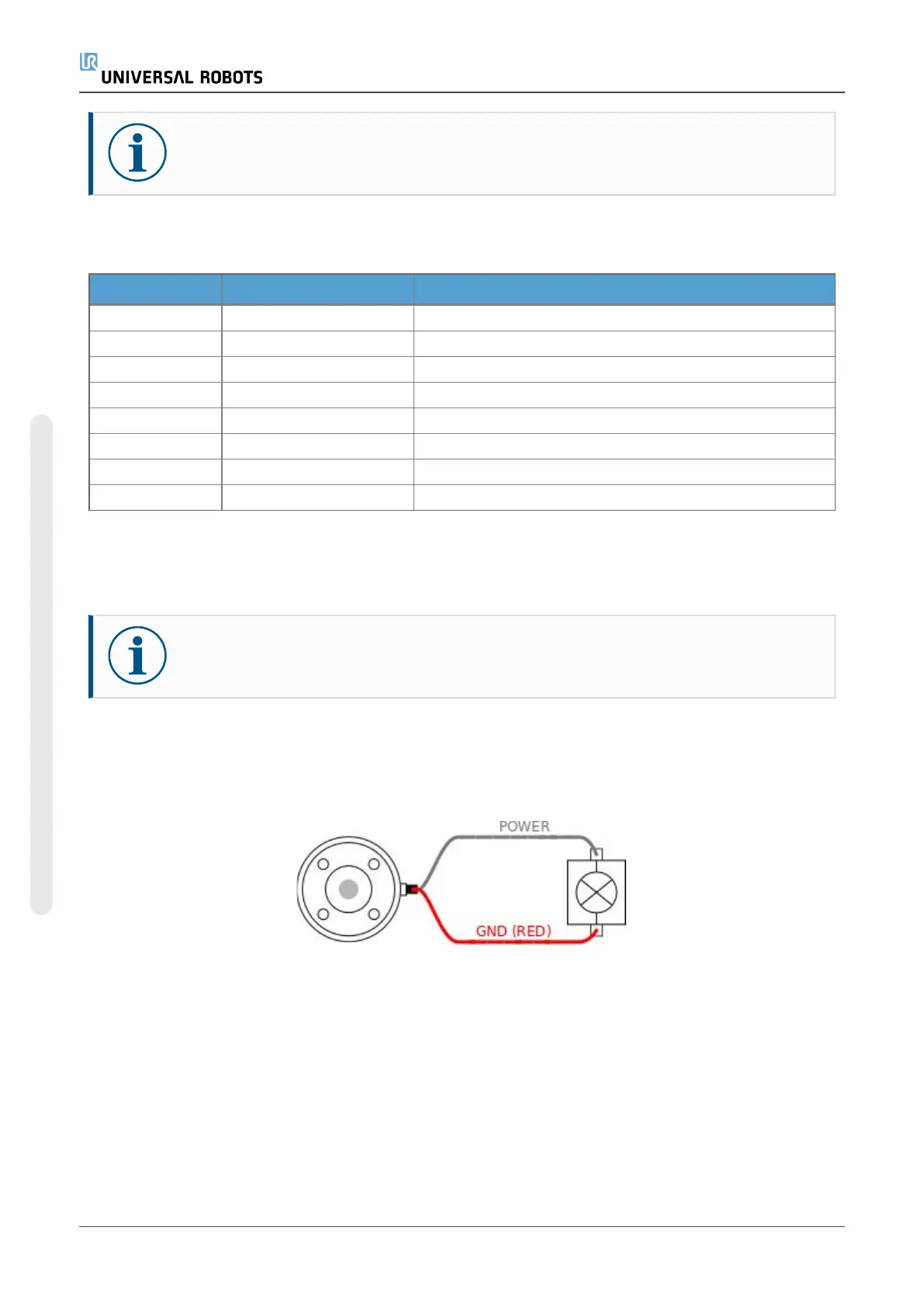
*It is highly recommended to use a protective diode for inductive loads.
NOTICE
The tool flange is connected to GND (same as the red wire).
Tool Power Supply
Access Tool I/O in the Installation Tab (see partPart II PolyScope Manual) to set the internal power
supply to 0V, 12V or 24V.
Dual Pin Power Supply
In Dual Pin Power mode, the output current can be increased as listed in (2.4.8. Tool I/Oon the
previous page table two).
1. In the Header, tap Installation.
2. In the list on the left, tap General.
3. Tap Tool IO and select Dual Pin Power.
UR5e User Manual
Copyright © 2009–2023 by UniversalRobotsA/S. All rights reserved.
 Loading...


