5-2 X-Series Work Platform
Troubleshooting
Section
Test Steering Switch for continuity.
Replace if faulty.
Test Diode. Replace if faulty.
Test Steer Right Solenoid. If the
proper voltage is present and the coil
is not magnetized, replace.
Test Steering Switch for continuity.
Replace if faulty.
Test Diode. Replace if faulty.
Test Steer Left Solenoid. If the proper
voltage is present and the coil is not
magnetized, replace.
Check continuity of Drive/Lift Switch.
Replace if faulty.
Test Relay (R2). Replace if faulty.
Inspect Drive Motor shafts, hubs, and
keys.
Check hydraulic pressure being
delivered to the Drive Motors. If
sufficient, replace Drive Motors.
Adjust and test the Level Sensor,
replace if faulty.
Check Relay, replace if faulty.
Check Pump, replace if faulty.
Adjust and test Controller.
Check continuity of Drive/Lift Switch.
Replace if faulty.
Check continuity of Down Limit
Switch. Replace if faulty.
Test coil and valve. If faulty, replace.
Check continuity of switch, replace if
faulty.
Check operation, adjust if necessary.
Replace if required.
Check operation, replace if required.
Test Relay (R2). Replace if faulty.
Check the Drive/Lift Valve. If the
spool is not shifting, replace the valve.
Check pressure of Counterbalance Valves.
Replace or reset valves as required.
Test Relay (R2) Replace if faulty.
Check operation of Controller switch.
Replace if required.
Test Relay (R2). Replace if faulty.
Check the Drive/Lift Valve. If proper
voltage is present and coil is not
magnetized replace the coil, if the
spool is not shifting, replace the valve.
Test diode, replace if faulty.
Check pressure of Counterbalance Valves.
Replace or reset valves as required.
Test Relay (R2). Replace if faulty.
Check operation of Controller switch.
Replace if required.
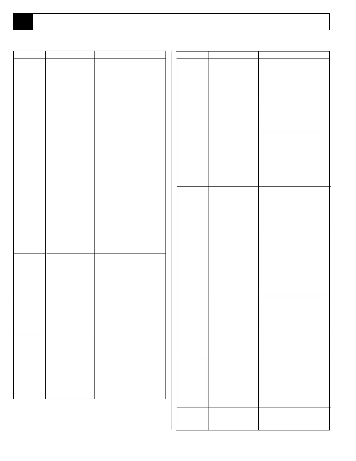
Table 5-1: Troubleshooting
Check control circuit Circuit Breaker.
Reset if open (button out).
Check 175 amp Electric Motor Fuse.
Replace if blown.
Check the voltage output of the
Battery Charger. If less than 24 VDC,
repair or replace.
After completely charging Batteries,
test each Battery. Replace as required.
While operating the steering function,
check voltage across the Electric
Motor terminals. If 24 VDC is
present, replace the Motor.
While operating the steering, check
voltage across the coil terminals of
Motor Relay. If no voltage is present,
proceed with step 7. If 20 VDC or
more, check continuity across the
contact terminals of Motor Relay
while still operating the steering
function. If there is no continuity,
replace the faulty Motor Relay.
With the Emergency Stop Switch in
the ON position, check continuity
across the contacts. If none, replace.
Check continuity of switch, replace if
faulty.
Test relay, replace if faulty.
Check continuity of switch, replace if
faulty.
Check operation, adjust if necessary.
Check hydraulic fluid level, top off as
required.
Check pressure and delivery of the
Hydraulic Pump. Replace if required.
Check operation, adjust if necessary.
Replace if required.
Check operation, replace if required.
Check operation. Adjust or replace if
required.
With 0 voltage at the coil terminals of
the Motor Relay (R1) check continuity
across the contact terminals. If there is
continuity, replace the Motor Relay.
Test Steering Switch for continuity.
Replace if faulty.
Inspect all steering components.
Replace damaged parts.
Inspect Steering Valve. If spool is
sticking, replace.
Check Steering Cylinder for leakage
from one port to another. Repair as
required.
Adjust the relief valve, if not
adjustable replace.
All functions
inoperable,
Electric Motor
does not start.
All functions
inoperable.
Electric motor
starts when
control is
actuated.
Electric Motor
continues to
run after
controls are
returned to the
OFF position.
Steering
inoperable or
functions
sluggishly.
TROUBLE
PROBABLE CAUSE
REMEDYTROUBLE
PROBABLE CAUSE
REMEDY
1. Open control circuit
Circuit Breaker (CB).
2. Blown Electric Motor
Fuse (FU1).
3. Faulty Battery
Charger.
4. Faulty Battery(ies)
(BAT).
5. Faulty Electric Motor
(MOT).
6. Faulty Motor Relay
(R1).
7. Emergency Stop
Switch failed open.
8. Faulty Down Limit
Switch (LS1).
9. Faulty Tilt Alarm
Relay (R3).
10. Faulty
Interlock Switch.
11. Faulty
Controller.
1. Hydraulic Reservoir
low.
2. Faulty Hydraulic
Pump (PMP).
3. Faulty Controller
(CONT).**
4. Proportional Valve
(V9,SOL8).**
Motor Relay (R1)
contacts fused
together.
1. Faulty Steering
Switch.
2. Mechanical damage.
3. Steering Valve (V1)
stuck.
4. Steering Cylinder
(CYL1) piston seal
leaking.
5. Steering Relief (RV2).
5.1
Work platform
will not steer
right.
Work platform
will not steer
left.
Work platform
will not drive
FORWARD or
REVERSE. Lift
function
operable.
Work Platform
will not drive
while elevated.
No high speed
drive.
No drive FWD
but drives in
REV. Lift
function
operable.
No drive FWD
but drives in
REV. No lift
function.
No drive REV
but drives in
FWD. Lift
function
operable.
No drive REV
but drives in
FWD. No
down function.
1. Faulty Steering
Switch.
2. Faulty Diode (D1).
3. Faulty Steer Right
Solenoid (SOL1).
1. Faulty Steering
Switch.
2. Faulty Diode (D2).
3. Faulty Steer Left
Solenoid (SOL2).
1. Faulty Drive/Lift
Selector Switch (S5).
2. Faulty Drive/Lift Relay
(R2).
3. Mechanical failure.
4 . Worn Drive Motors (
MOT1, MOT2).
1. Level Sensor (SNSR)
out of adjustment or
faulty.
2. Faulty Relay.
3. Low Segment of
pump faulty.
4. Controller Adjustment**
1. Faulty Drive/Lift
Switch.
2. Faulty Down Limit
Switch (LS1).
3. Faulty High Speed
Coil/Valve (SOL7/V6).*
4. Faulty Controller
Switch (S4).*
5. Faulty Controller
(CONT).**
6. Proportional Valve
(V9,SOL8).**
1. Faulty Drive/Lift Relay
contacts (R2).
2. Faulty Forward/
Reverse Valve (V5).
3. Faulty Counterbal-
ance Valves (V2, V3).
1. Faulty Drive/Lift Relay
contacts (R2)
2. Faulty Up/Forward
Controller Switch (S9).
1. Faulty Drive/Lift Relay
contacts (R2).
2. Faulty Forward/
Reverse Solenoid/
Valve (SOL3/V5).
3. Faulty diode (D3).
4. Faulty Counterbalance
Valves (V2, V3).
1. Faulty Drive/Lift Relay
contacts (R2).
2. Faulty Down/Reverse
Controller Switch (S2).
 Loading...


