Do you have a question about the US Robotics COURIER and is the answer not in the manual?
Discusses the role of communications software and user preferences for modem control.
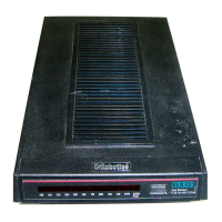
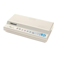
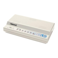
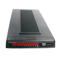
Overview of the Courier modem's advanced design, reliability, and flexibility.
Explains how ASL monitors line quality and adjusts modem speed for optimal performance and data integrity.
Ensures data integrity through V.42 (LAPM), USR-HST, or MNP error control protocols.
Details adherence to standards like USR-HST, CCITT V.32 bis, V.32, and V.22 bis for broad modem compatibility.
Lists items included in the Courier modem package, in addition to the manual.
Specifies the need for an RS-232 cable and details pin assignments for computer/terminal connection.
Explains the functions of the Voice/Data pushbutton and Volume Control slide switches.
Lists and describes the modem's twelve status lights (LEDs) and their operational meanings.
Provides step-by-step instructions for physically connecting the modem to the computer and phone line.
Guides users through procedures to confirm the modem is working correctly after installation.
Details factory-set compatibility configurations for Dual Standard, V.32 bis, and HST modems.
Provides optimal settings for best data reliability and throughput, focusing on DTE rate and hardware flow control.
Covers commands for dialing numbers, including pulse/tone dialing and redialing.
Describes how modems negotiate the highest possible link rate based on capabilities.
Explains modulation types and settings for V.32 bis and HST, including speed and channel asymmetry.
Provides guidelines to achieve optimal throughput by leveraging fixed DTE rates, data compression, and file types.
Details error control options, including Normal/ARQ modes and their impact on connection reliability.
Covers hardware and software flow control methods to manage data transmission from the DTE to the modem.
Enables data compression for increased throughput, with options for V.42 bis and MNP5.
Configures the DTE interface rate as variable or fixed, impacting connection speed and compatibility.
Sets the link interface rate as variable or fixed, allowing connection with various remote modems.
Saves user-defined configurations to NVRAM for power-on defaults using the &W command.
Controls how the modem reports connection status and events to the screen via numeric or verbal codes.
Controls the display of typed commands (Command Mode) or transmitted data (Online) on the screen.
Explains the use of S-Registers for setting timing parameters and other configuration options.
Lists the supported modulation standards and signaling protocols the Courier modem adheres to.
Guides users on setting terminal/software rates to match the modem's highest speed for optimal throughput.
Covers dialing commands, including number entry, canceling dialing, and using optional parameters.
Details methods for redialing, including last dialed number, automated redialing, and continuous repeat.
Explains how to use the +++ escape code to return to Command mode from an online session.
Explains how to configure the modem for synchronous operation before establishing a network connection.
Provides guidelines for setting modulation and link rates for V.32 bis, HST, and Dual Standard modems.
Explains commands to retrieve information like call duration, settings, NVRAM contents, and link diagnostics.
Describes how to access summaries of AT, ampersand, S-Register, and Dial command sets.
Lists essential AT commands for modem control, such as Attention, Dial, and Hang Up.
Explains the handshaking process for HST connections, including speed adjustments and error control.
Describes V.32 bis handshaking adhering to CCITT recommendations and proprietary enhancements.
Details error control availability, operations like compatibility establishment, and data frame formatting.
Details RS-232 pin assignments for DB-25 and DB-9 connectors, specifying signal flow.
Describes the meaning and status of each modem indicator light (LED) for operational feedback.
Provides a summary of DIP switch functions, factory settings, and their impact on modem operations.
Lists S-Registers, their default values, and functions for configuring modem behavior.
Lists fundamental AT commands for modem control, such as Attention, Dial, and Hang Up.
Addresses issues like modem not dialing or not responding to AT commands, guiding through checks and settings.
Addresses scenarios where modems exchange carrier signals but fail to establish a link, suggesting checks and settings.
Provides solutions for data display problems like only brackets or random/garbage characters.
Recommends reviewing the manual, contacting dealers, or USRobotics Technical Support for persistent issues.
Guides on using the fax modem with compatible software and switching between fax and data modes.
Explains how to use the voice/data switch and AT commands for toggling between voice and data calls.
Details setting up and using remote configuration, including password security and login attempts.
Explains how modems switch link rates to match calling modems and how computers can be programmed to do so.
Covers modem operations on non-switched telephone lines, including user-installed and leased lines.
Covers analog loopback, digital loopback, and remote digital loopback tests using the &T command.
Details analog loopback tests, including typing data or using internal test patterns for transmitter/receiver verification.
Verifies conditions of modems and phone links using remote digital loopback, requiring CCITT V.22 signaling.
Utilizes S16 as a bit-mapped register for selecting various tests like Analog Loopback and Dial Test.
Techniques for checking character or data block reliability using V.42, MNP, HST protocols.
USRobotics proprietary signaling, design, and error control for high-speed modems with asymmetrical modulation.
Asynchronous error control protocol ensuring error-free transmission via detection and retransmission.
User-programmable memory retaining data when power is off, used for default configurations.
Allows remote users to view and change modem configuration, with password protection available.
CCITT standard for modem communications defining LAPM error control and supporting MNP levels 1-4.
Extension of V.42 defining data compression for V.42 and MNP error control.
Details HST specifications including speeds, modulation, and back channel adjustments.
Lists V.32 bis specifications including speeds, modulation, and synchronization methods.
Lists the supported serial port data rates for the DTE interface.
Specifies the link rates supported by the modem for Data Mode and Fax Mode.
Lists the various operational modes supported by the Courier modem, including synchronous, asynchronous, and fax.
Provides a list and explanation of the status lights on the modem's front panel.
| Model | COURIER |
|---|---|
| Maximum Data Rate | 56 Kbps |
| Fax Protocols | V.17, V.29, V.27ter, Group 3 |
| Error Correction | V.42, MNP 2-4 |
| Data Compression | V.42bis, MNP 5 |
| Interface | Serial (RS-232) |
| Form Factor | External |
| Data Protocols | V.90, V.34, V.32bis, V.32, V.22bis, V.22, V.21, Bell 212A, Bell 103 |
| Features | Caller ID, Distinctive Ring |