Do you have a question about the USTER HVI 1000 and is the answer not in the manual?
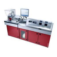
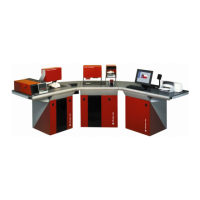
Introduces the USTER HVI 1000 system and its capabilities for fiber testing.
Lists the features and components available on the HVI 1000 system.
Describes the L/S, Micronaire, Color, and Trash modules of the HVI 1000 system.
Outlines the capabilities and components of the HVI 1000 system software.
Covers general safety precautions and warning labels for the HVI 1000 system.
Provides an overview of the HVI 1000 system shipping and installation process.
Specifies the voltage, amperage, and circuit requirements for the HVI 1000 system.
Outlines the recommended environmental conditions for operating the HVI 1000 system.
Details the compressed air specifications needed for the HVI 1000 system operation.
Explains how to connect peripherals like the balance, monitor, and keyboard to the system.
Details the correct sequence for powering on the HVI 1000 system.
Introduces the HVI 1000 system's need for specific training and proper setup.
Describes the four major areas of the system's main menu interface.
Details the functionality and options available within the system's menu bar.
Lists the six primary functions of the HVI 1000 software.
Explains how to define important operating parameters for system testing.
Describes the routine calibration procedures performed at the start of a shift.
Explains the process for regular system testing of fibers.
Describes how to configure, view, and print reports from test data.
States that this area is for troubleshooting and system maintenance.
Introduces the Configuration Menu for defining important operating parameters.
Details setting options for system testing, including repetitions and limits.
Describes how to set or change the supervisor password for configuration.
Explains how to set up serial port parameters and data transmission.
Describes the four different modes available for system testing.
Explains how lot limits establish ranges for legitimate property values in testing.
Details how two-sided retests apply only to system testing.
Covers making small adjustments to measured values for system testing.
Details configuring minimum and maximum ranges for data alarms.
Emphasizes the necessity of module calibration for initial startup and standards changes.
Explains the close-ended calibration process for LS, CT, and Mic modules.
Describes accessing calibration options for different modules.
Covers the calibration process for the Length/Strength module.
Details the procedure for calibrating the micronaire unit using calibration cottons.
Outlines the simple calibration procedure for color and trash measurements.
Introduces system testing for HVI 1000, covering its modules and testing modes.
Details the main menu for initiating and configuring system testing.
Describes the four available testing modes for system testing.
Discusses the common elements and appearance of testing screens across different modes.
Explains how background colors indicate module status during testing.
Describes the interface and elements of Mode 1 testing.
Explains how to retest bales with discrepant data or limit violations.
Describes the interface and elements of Mode 2 testing.
Describes the interface and elements of Mode 3 testing.
Describes the interface and elements of Mode 4 testing.
Details the procedures for entering Bale ID, Micronaire, L/S, and Color/Trash tests.
Explains performing Length/Strength tests as individual observations.
Details the steps for performing an LS module test.
Explains how to reject the latest measurement within a module test.
Explains performing Micronaire tests as individual observations.
Details the steps for performing a MIC module test.
Explains performing Color/Trash tests as individual observations.
Details the steps for performing a Color/Trash module test.
Details the data interface with the 720 NEP Tester for counting Neps.
Details the data interface with the 380 Fibroglow for measuring fiber fluorescence.
Explains the Diagnostics section for troubleshooting system hardware.
Lists options for checking motors, control boards, and updating firmware.
Covers troubleshooting motors, optics, air systems, and updating firmware.
Details troubleshooting the bar code reader for Bale ID entry.
Explains testing the Color Head functionality, including image capture.
Describes searching for the best pot setting for optics.
Details setting up the Mic air or micronaire chamber.
Explains checking digital inputs, outputs, and voltages of control boards.
Details taring moisture channels and performing tests for M1000.
Covers testing and operating various motors independently.
Details updating firmware for Mic, L/S, and Moisture modules.
Introduces the main menu areas for the Report Launcher.
Details the options available in the Report Launcher's menu bar.
Lists the functionality options available on the Report Launcher toolbar.
Explains the use of the favorites bar for quick access to configured reports.
Guides on mapping existing reports to favorite buttons.
Explains how to navigate, print, zoom, and search within reports.
Covers essential setup items like language, default folder, and printer.
Covers opening, printing, editing, and configuring reports.
Describes the methods for opening and viewing reports.
Lists available report templates for various test groups.
Lists routine tasks for keeping instruments in top condition.
Details procedures for removing excess fiber after each shift.
Explains daily tasks for keeping the lint/waste box clean.
Discusses the importance of calibration tiles for color and trash measurements.
Provides detailed instructions for cleaning calibration tiles.
Explains that service should be performed by qualified technicians.
Defines calibration as checking or correcting measurement graduations on the instrument.
Defines elongation based on stress-strain curve and break gage.
Defines length in HVI testing based on selected span lengths.
Defines micronaire value associated with cotton fineness using air-flow.
Defines strength as breaking force relative to fiber mass.
Defines trash as the non-fiber portion of cotton.
Defines uniformity as the ratio of two length measurements.
Defines UHML as the average length of the longer half of fibers.
Covers spectrum support and transmission interactions for data.
Divides HVI records into Head, Body, and Tail sections.
Describes the header format for transmitted records.
Lists supported record body data for Length/Strength, Micronaire, etc.
Defines fields and types for Length/Strength individual observations.
Defines fields and types for Micronaire individual observations.
Defines fields and types for Color & Trash individual observations.
Divides the Error Handle screen into four basic areas.
Lists specific error codes associated with control boards.
Lists three options for error recovery: Retry, Ignore/Continue, Reset.
Provides a table of error messages and their corresponding actions.
| Brand | USTER |
|---|---|
| Model | HVI 1000 |
| Category | Test Equipment |
| Language | English |