Chapter 3: Controls and Features
VS2000 Vital Signs Monitor Operation Manual 3-5
Connector (T1
up and T2 low)
the patient connector is attached to the monitor. A
measured value for temperature (TEMP) will be
sensor is attached to the patient
3
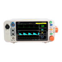
Non-Invasive
Blood Pressure
Connector
(NIBP)
Attach the NIBP cuff to the monitor. Measured values for
non-invasive blood pressure (systolic, diastolic, and
mean) will be displayed when the most recent NIBP
measurement is complete.
4
ECG Connector Attach the ECG leads to the monitor. A measured value
for the ECG heart rate (HR) will be displayed when the
ECG leads are attached to the patient.
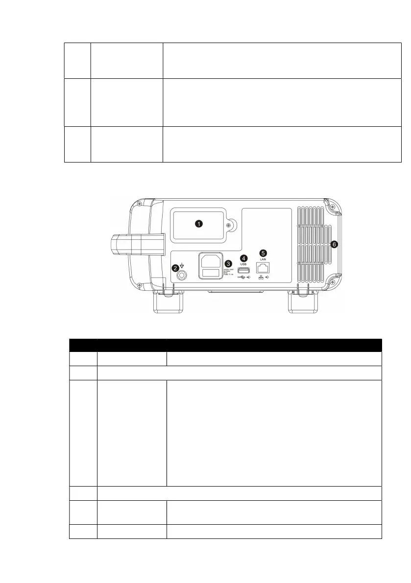
3.4 Back Panel
Figure 3.5: Back Panel
NO. DESRIPTION INSTRUCTION
Battery The monitor is equipped with a lithium battery.
Equipotential Grounding
3
AC Power
Connector
Plug the AC power cord into the AC power
receptacle at the back of the monitor. When the
other end is plugged into a ground, three wire
hospital-grade outlet, the AC Power LED will light.
The monitor automatically switches between 100V
and 240V AC line voltage sources.
WARNING! Do not plug the monitor into an
outlet controlled by a wall switch.
USB Connector
5
Network
Connect to the central monitor.
Air Vents The monitor has air vents at the top of the back