List of Figures
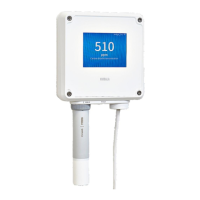
Figure 1 Indigo 201 With and Without Display, Wireless Interface
Examples............................................................................................................... 7
Figure 2 Serial Number on Probe Body (GMP251 Example)....................................9
Figure 3 Indigo Transmitter Parts..................................................................................10
Figure 4 Indigo 201 Display with One Parameter ......................................................11
Figure 5 Indigo 201 Display with Relays, Three Parameters and
WLAN Notification............................................................................................. 11
Figure 6 Indigo Display in Graph Mode........................................................................ 12
Figure 7 Purge in Progress Message from Probe on Indigo Display.................... 13
Figure 8 Desktop and Mobile Example Views............................................................ 15
Figure 9 Clearing Analog Output Settings .................................................................16
Figure 10 Indigo 201 Transmitter Base Main Parts and Screw Positions...............18
Figure 11 Indigo Wiring Options......................................................................................19
Figure 12 Attaching Probes and Cables to Indigo..................................................... 20
Figure 13 WLAN OFF/ON DIP Switch on Indigo Circuit Board...............................22
Figure 14 Wireless Configuration Interface, Desktop Browser View.....................25
Figure 15 Enabling and Accessing Indigo's Wireless Configuration Interface... 26
Figure 16 Indigo Login View.............................................................................................28
Figure 17 User Level (User/Admin) in Upper Right Corner of Menu View...........29
Figure 18 Measurements View (Desktop Browser).....................................................31
Figure 19 Latest Values Tab, H
2
O
2
Probe Example (Desktop Browser)................ 31
Figure 20 Status View (CO
2
Probe Example, Desktop Browser)............................32
Figure 21 Calibration Menu (CO
2
Probe Example, Desktop Browser).................. 35
Figure 22 Analog Output Configuration Options.......................................................45
Figure 23 Example of Analog Output Overrange Behavior ....................................48
Figure 24 Relay Configuration Options (CO
2
Probe Example)...............................49
Figure 25 Relay Icons on the Optional Display (Relay A Active, Relay
B Not Active)..................................................................................................... 50
Figure 26 Calibration Menu Main View...........................................................................53
Figure 27 Start Calibration Button..................................................................................54
Figure 28 Measurement Selections, CO
2
Probe Example......................................... 57
Figure 29 Compensation Setpoint and Power-Up Default Selection,
CO
2
Probe Example..........................................................................................58
Figure 30 Measurements Tab, CO
2
Probe Example....................................................59
Figure 31 Diagnostics Tab, CO
2
Probe Example......................................................... 60
Figure 32 Configuration Tab, CO
2
Probe Example...................................................... 61
Figure 33 Additional Steps Needed to Connect Notification..................................66
Figure 34 Indigo Transmitter Dimensions in Millimeters (mm)...............................74
List of Figures
3

 Loading...