805
REVO-E Heat pump 8 Removal/ installation of components (high-volt. syst.)
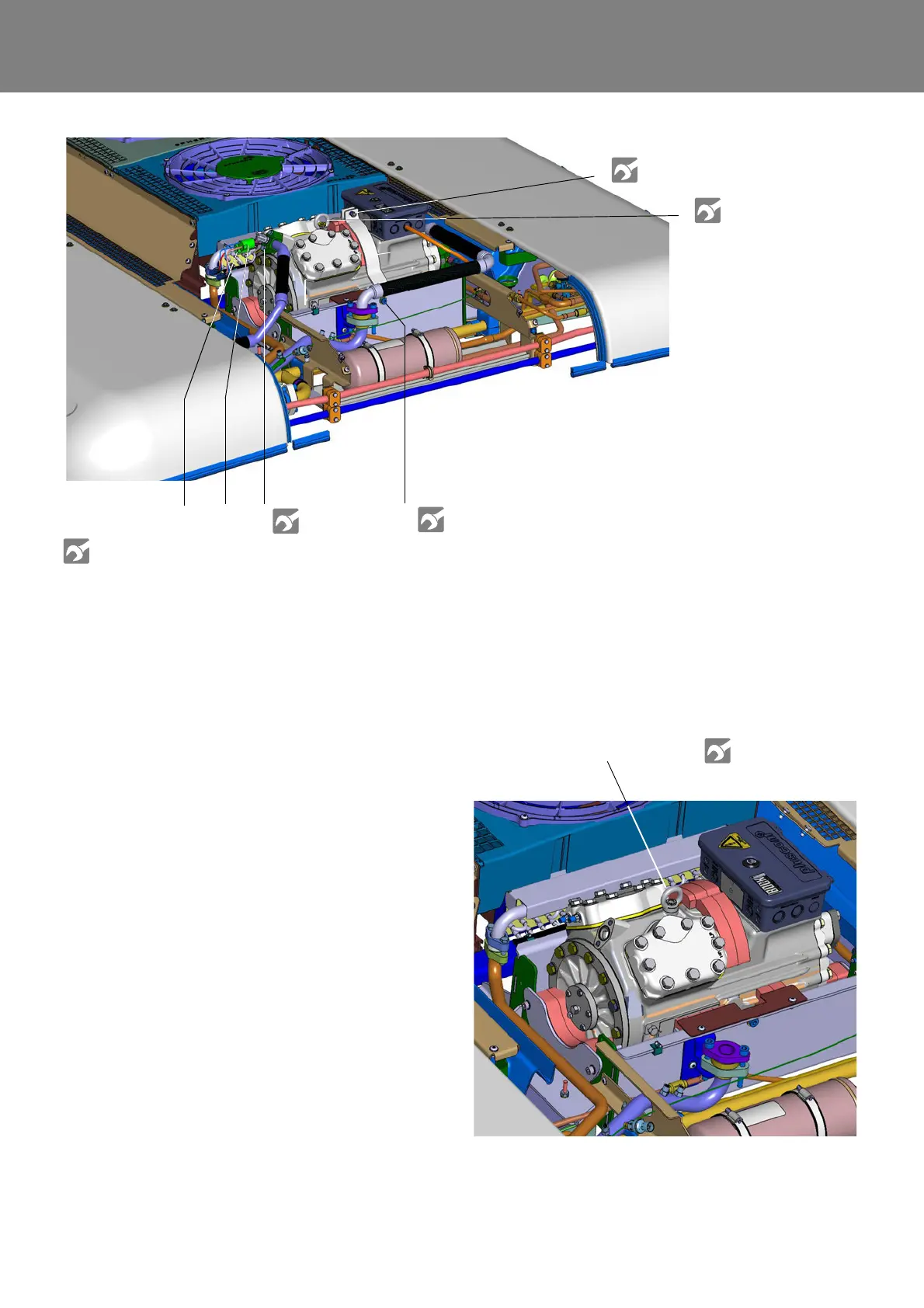
3. Remove attachments / connections
• Remove 24V cables from compressor pan (not
pictured).
• Remove screws (2) that attach the retaining clamp
to the compressor pan and remove retaining clamp.
• Suction line (see 9.13).
• Remove screws (4) that hold the pressure plate on
the compressor and remove pressure plates.
• Fluid line (see 9.13).
• Low / high pressure switch (see 9.12).
• Remove screws (6 and 10) that hold the mounting
bracket and remove mounting bracket.
• Separate grounding cable by pulling out ring
screws (7) from compressor housing, screw ring
screws back in.
4. Removing compressor
• Lift compressor at the ring screw (7) from
compressor pan with suitable lifting device.
NOTE:
Ensure components of the compressor mounting do
not fall.
Fig. 806
6 Screw + locknut of mounting bracket
7 Ring screw / transport lug / grounding
8 Screws for compressor fluid lines
9 Low pressure switch (not at 11123865_)
10 Screws for mounting bracket of compressor
(both sides)
11 High pressure switch
6
7
8
9
1011
See torque table
Attachment A
Fig. 807
Ring screw / transport lug