VAMP 24h support phone +358 (0)20 753 3264
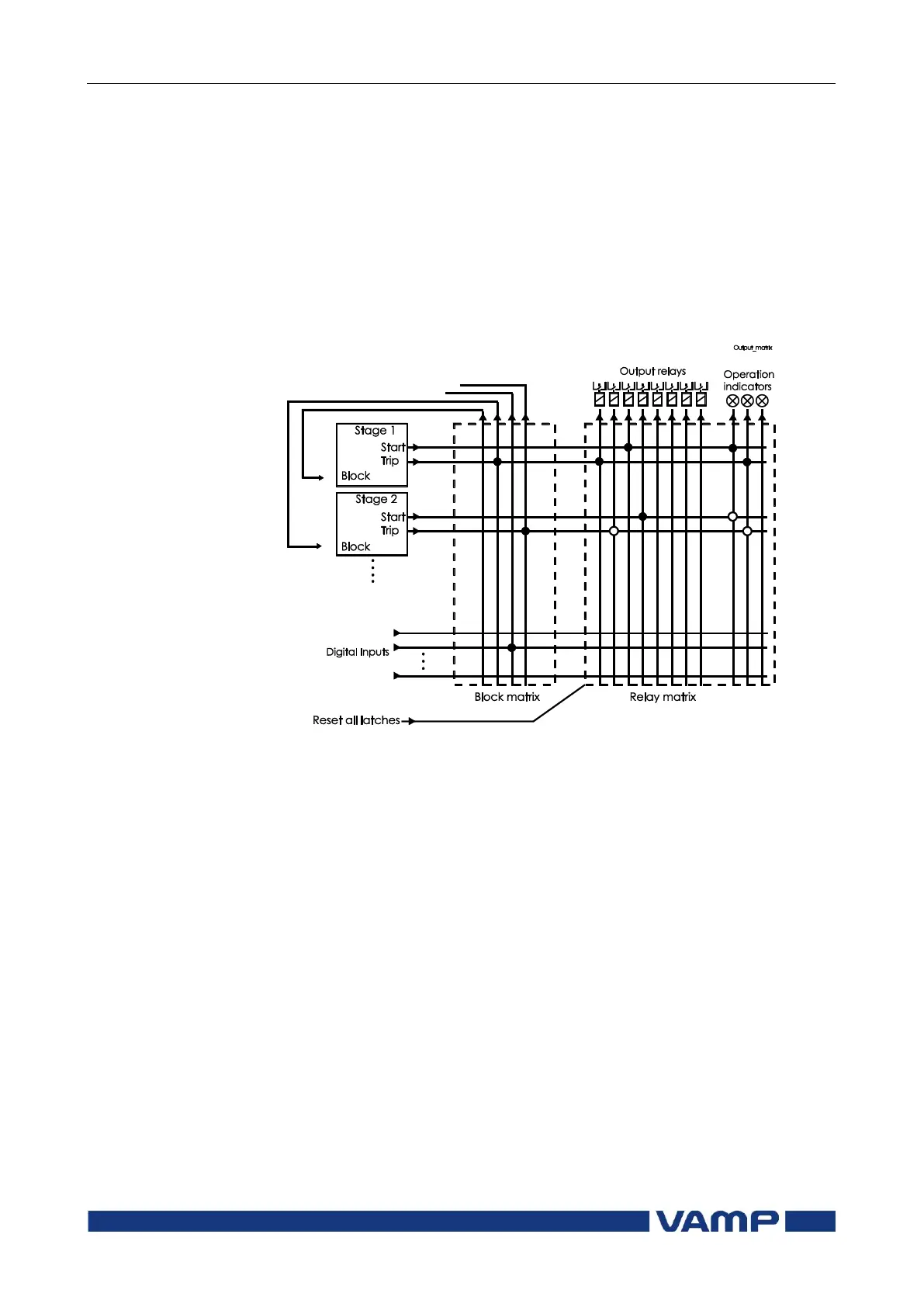
5.5. Blocking matrix
By means of a blocking matrix, the operation of any protection
stage can be blocked. The blocking signal can originate from
the digital inputs DI1 to DIn (see chapter order code), or it can
be a start or trip signal from a protection stage or an output
signal from the user's programmable logic. In the block matrix
Figure 5.5-1 an active blocking is indicated with a black dot (•)
in the crossing point of a blocking signal and the signal to be
blocked.
Figure 5.5-1 Blocking matrix and output matrix
5.6. Controllable objects
The device allows controlling of six objects, that is, circuit-
breakers, disconnectors and earthing switches. Controlling can
be done by "select-execute" or "direct control" principle.
The logic functions can be used to configure interlocking for a
safe controlling before the output pulse is issued. The objects
1...6 are controllable while the objects 7...8 are only able to
show the status.
Controlling is possible by the following ways:
o through the local HMI
o through a remote communication
o through a digital input.
The connection of an object to specific output relays is done via
an output matrix (object 1-6 open output, object 1-6 close
output). There is also an output signal ―Object failed‖, which is
activated if the control of an object fails.