2.5 Line differential protection LdI>
(87)
VAMP 24h support phone +358 (0)20 753 3264
2.5. Line differential protection LdI> (87)
Line differential protection (LDP) provides high speed clearing
for faults occurring at any point on a transmission line.
The line differential protection unit uses voltage measurements
to calculate the resistive part of each of the three phase
currents. The dedicated communication channel, called pilot
channel, is used between two relays to exchange information on
resistive phase currents and to determine whether the fault is
internal or external to the protected line. In each piloting relay
the difference between the corresponding resistive phase
currents from this unit and from the remote unit is computed
and compared against the configured threshold. In case any of
the phases shows the difference in resistive currents greater
than the threshold, the relay trips after the configurable
operation time.
The measurement and transmission operations in the two
piloting relays are not synchronized. Therefore, the
communication speed on the pilot channel should be high
enough to minimize the impact of fault detection delay
asymmetry. The default communication speed is 38400 bps.
Using the lower speed may result in longer minimum operation
time of the relay.
Serial remote port of the relay is used by line differential
protection.
The recommended solution for the pilot channel is the
supervised fibre optic wiring. With multimode fibre cables and
VSExxx-GG fibre optic modems the communication distance
can be up to 1 km. When using single mode fibre cables and
third party modems the distance can be up to tens of
kilometres.
Using resistive currents for comparison assures good
insensitivity to line capacitive charge currents.
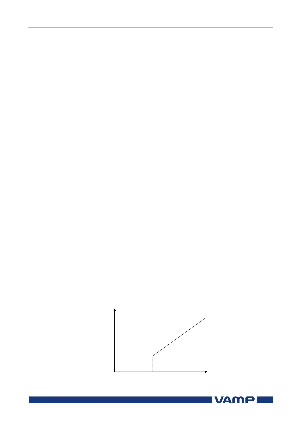
The threshold characteristics is biased for CT saturation as
presented in Figure 2.5-1 .
dI> pick-up
(Basic setting)
Start of slope (Basic limit)
Figure 2.5-1 LDP tripping threshold characteristics