Operation and configuration
2 Local panel user interface
VAMP 24h support phone +358 (0)20 753 3264
2.1.4. Operation Indicators
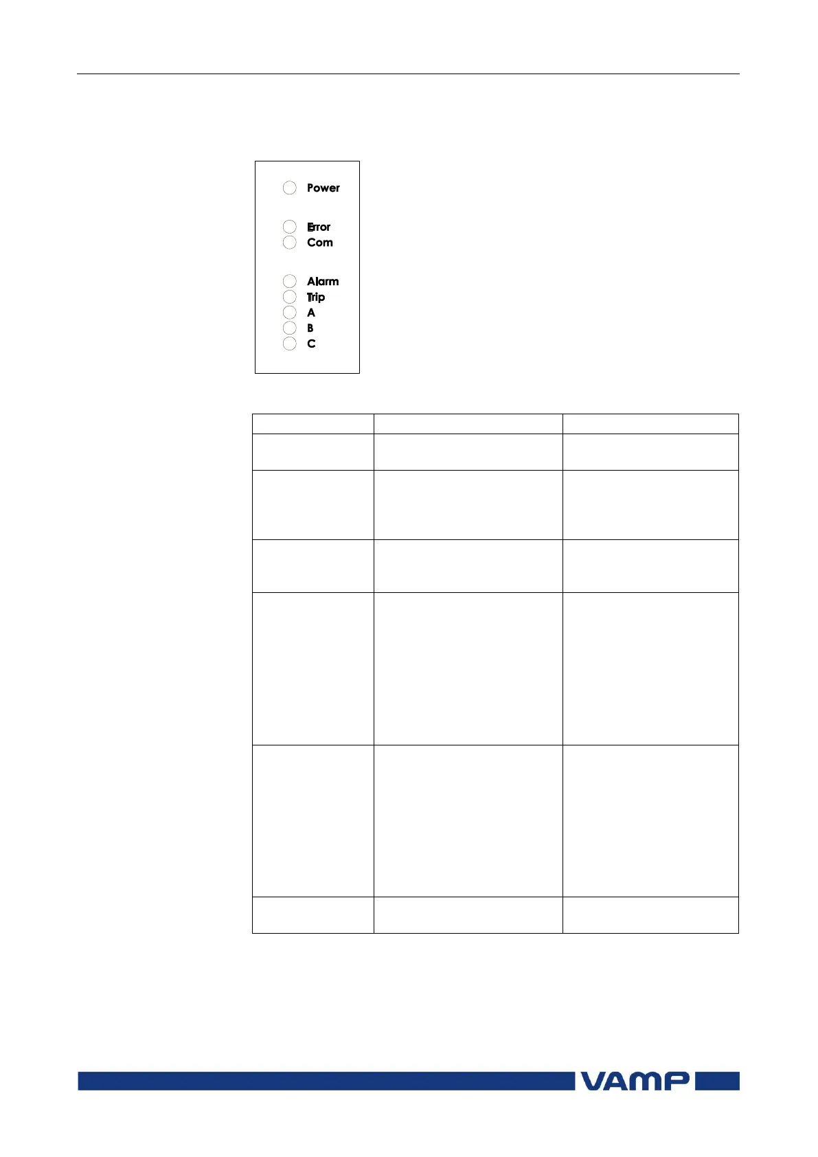
The relay is provided with eight LED indicators:
Figure 2.1.4-1. Operation indicators of the relay
The auxiliary power has
been switched on
Internal fault, operates in
parallel with the self
supervision output relay
The relay attempts to
reboot [REBOOT]. If the
error LED remains lit,
call for maintenance.
The serial bus is in use
and transferring
information
One or several signals of
the output relay matrix
have been assigned to
output LA and the output
has been activated by one
of the signals. (For more
information about output
matrix, please see chapter
2.4.5).
The LED is switched off
when the signal that
caused output Al to
activate, e.g. the START
signal, is reset. The
resetting depends on the
type of configuration,
connected or latched.
One or several signals of
the output relay matrix
have been assigned to
output Tr, and the output
has been activated by one
of the signals. (For more
information about output
relay configuration, please
see chapter 2.4.5).
The LED is switched off
when the signal that
caused output Tr to
activate, e.g. the TRIP
signal, is reset. The
resetting depends on the
type of configuration,
connected or latched.
Application-related status
indicators.