2 Local panel user interface
Operation and configuration
VAMP 24h support phone +358 (0)20 753 3264
2. Local panel user interface
2.1. Front panel
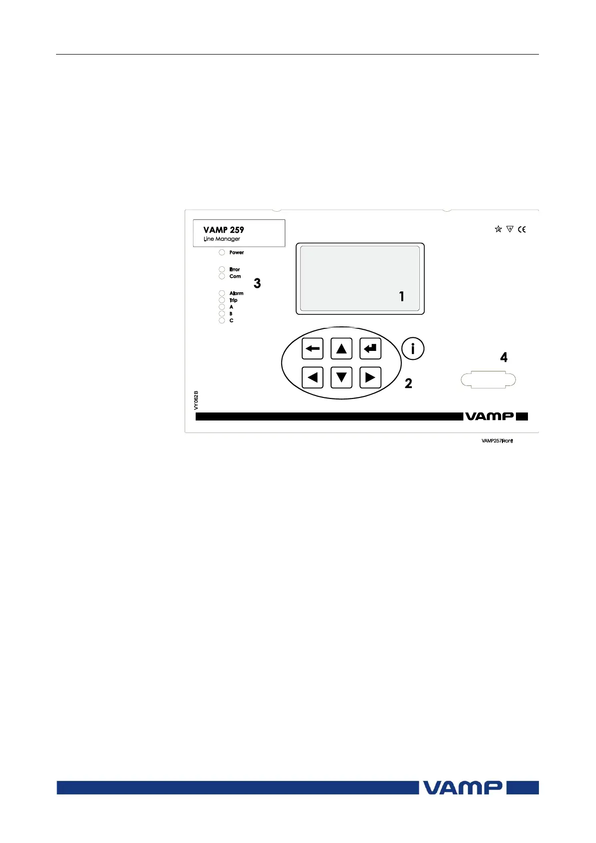
The figure below shows, as an example, the front panel of
VAMP 259 and the location of the user interface elements used
for local control.
Figure 2.1-1. The front panel of VAMP 259
1. LCD dot matrix display
2. Keypad
3. LED indicators
4. RS 232 serial communication port for PC
2.1.1. Display
The relay is provided with a backlightedt 128x64 LCD dot
matrix display. The display enables showing 21 characters in
one row and eight rows at the same time. The display has two
different purposes: one is to show the single line diagram of the
relay with the object status, measurement values, identification
etc. (Figure 2.1.1-1). The other purpose is to show the
configuration and parameterization values of the relay (Figure
2.1.1-2).