8.3 Serial communication connection
VAMP 24h support phone +358 (0)20 753 3264
NOTE! Profibus will be supported by the external VPA 3CG module. This is
connected with a VX007-F3 cable to VCM TTL module ( VCM TTL dip-
switch must be set to TTL).
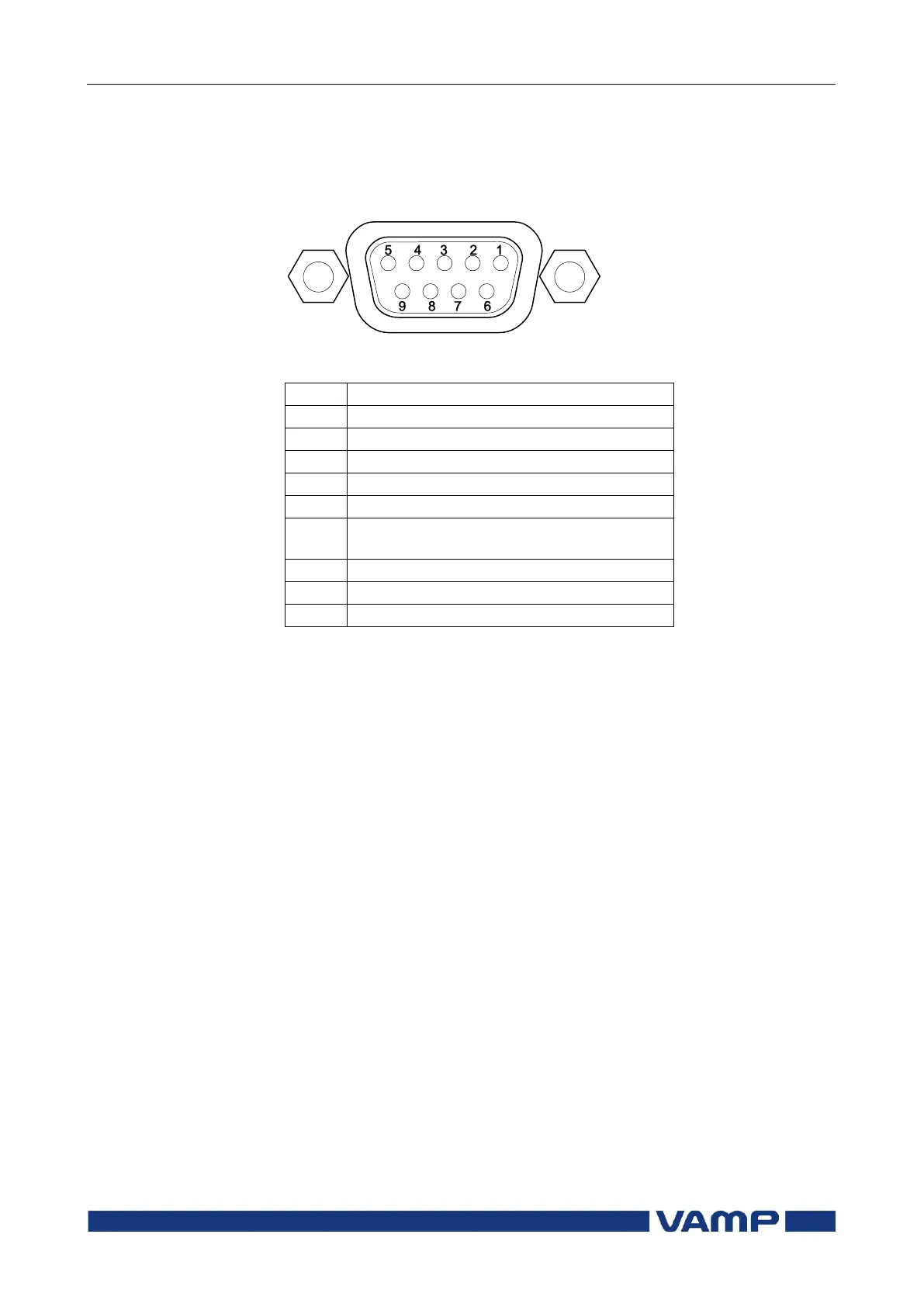
8.3.2. Front panel connector
Figure 8.3.2-1 Pin numbering of the front panel D9S connector
DSR in (activates this port and disables
the X4 RS232 port)
RTS in (Internally connected to pin 8)
CTS out (Internally connected to pin 7)
NOTE! DSR must be connected to DTR to activate the front panel connector and
disable the rear panel X4 RS232 port. (The other port in the same X4
connector will not be disabled.)