2.8 Current unbalance stage I2> (46)
VAMP 24h support phone +358 (0)20 753 3264
2.8. Current unbalance stage I
2
> (46)
The purpose of the broken line protection is to detect
unbalanced load conditions, for example a broken conductor of
a heavy loaded overhead line in case there is no earth fault.
The operation of the unbalanced load function is based on the
negative phase sequence component I
2
related to the positive
phase sequence component I
1
. This is calculated from the phase
currents using the method of symmetrical components. The
function requires that the measuring inputs are connected
correctly so that the rotation direction of the phase currents are
as in chapter 8.9. The unbalance protection has definite time
operation characteristic.
, where
I1 = I
L1
+ aI
L2
+ a
2
I
L3
I2 = I
L1
+ a
2
I
L2
+ aI
L3
, a phasor rotating constant
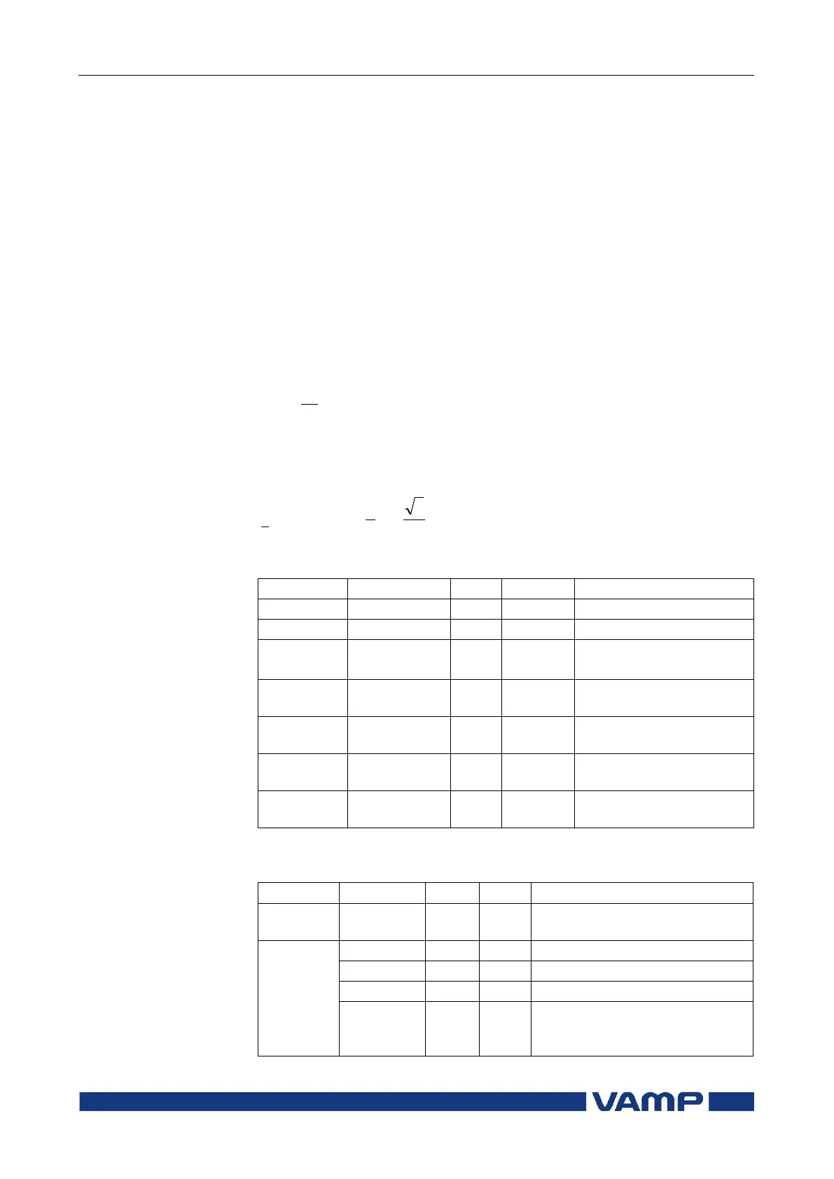
Setting parameters of current unbalanced stage I
2
> (46):
The selection of time
characteristics
Measured and recorded values of current unbalanced stage
I
2
> (46):
Relative negative sequence
component
Maximum I
2
/I
1
fault component
Elapsed time as compared to
the set operating time, 100% =
tripping