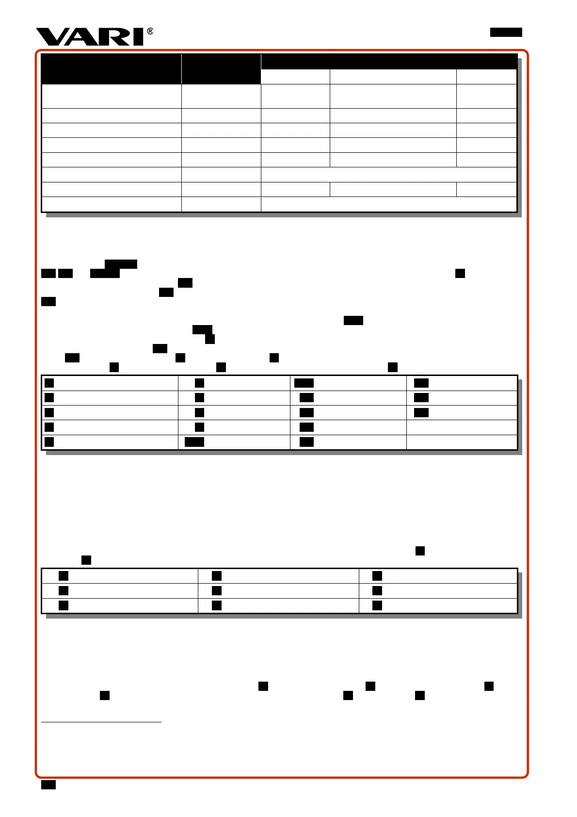
[ 3%
:PML :PML:PML :PML
Type -
HONDA
78
X3LSR
Briggs & Stratton
79
VSP] Series™ / VSP Series™
VARI
80
]MRR
Maximum (set) engine rpm min
-1
3200 ± 100 3200 ± 100 3200 ± 100
Maximum engine tilt (long period)
20° 15° 15°
Maximum engine tilt (short period
81
)
30° 30° 30°
Fuel tank volume l (litre) 0,91
82
1 1
Fuel (unleaded) petrol
83
ON 91-95
Engine oil filling l (litre) 0,4 0,6 0,6
Oil quality SAE / API SAE 10W-30 / SJ or SH
0!P)""%.
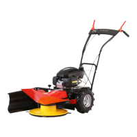
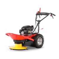
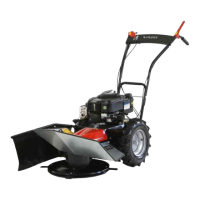
3.3.2 DESCRIPTION OF THE MACHINE AND ITS PARTS
Drum mower (
"!M
) is built on a steel frame, to which all important parts of the machine are attached. All "%
LV,LS and LR are placed on the handlebars. Handlebars are attached to the frame with a %& ""S and their height
is adjustable into 6 positions. Z&%LL secure a firm grip and machine handling during work. On the left side of the handlebars, there
is the %&"%" lever LS which controls the movement of the machine in forward direction. On the right side, there is lever
LS of the disc drive clutch for turning the cutting disk drive on (off). Both control levers return to their original position when the
handlebars are released in a critical situation and disconnect the engine power transfer. The cutting disk is equipped with an "
84
which stops the disk. Engine speed is controlled with an ""%%LR or, if the engine is equipped with an electric
starter, with a switch on the starting panelLR. The engine is started either by hand (by pulling a rope on the fan flywheel) or electric
(:PML only) with a starter and a battery Y. The wheel drive is controlled by worm-gear unit with a belt clutch which provides fluent
power transfer onto the wheels LP (the machine does not start with a jump). The gearbox and clutch are covered by a plastic a
"LO. There is the "&O with four %%&P in the front part. The attendant is protected against flying parts of the
cut stand by "L. A detachable &"N, which is attached with a %&""W, controls the line spacing.
L Upper cover of the cutting disc V Drive cover LR Starting panel (
"!W
) LP Wheel
M Front handgrip / strap S Handlebar bolt LL Handle LV Disc drive lever
N Side screen with holder Y Engine / Battery LM Frame - tube LS Wheel drive lever
O Cutting disc W Side screen bolt LN Petrol tank cap
P Blade (4 pcs) LR Accelerator lever LO Gearbox cover
0!V)&"!M
3.4 USER GUIDE
3.4.1 ASSEMBLING THE MACHINE
-.-:%";1&%-"&1.
@
Places for holding the cutter while removing it from the box (see
"!L
): by the cutting disc in the front L, by the machine frame tube
in the back M.
L Front grasp point O Battery – DS-521BiS only S Long screen and short screen
M Rear grasp point P Upper cover of the disc Y Battery charger – DS-521BiS only
N Tilted handlebars V Bag with small parts W Screen holder
0!S)&"!L
3.4.1.1 ASSEMBLING PROCEDURE
Use the following procedure for assembling the machine:
(It is advised to assemble the machine with a second person’s assistance)
Instructions “on the right” and “on the left” are meant from the point of the operator.
1. As per
"!L
- take both parts of the disc cover P, the bag with small parts V, side screen and rear screen S, screen
holder W out of the carton box; for :PML only: take out the battery O with the charger Y as well. Remove the carton
insert which is placed between the handlebars and the engine in the box.
SY
More information about the engine (including the spare parts numbers) can be found at !&::!".
SW
More information about the engine (including the spare parts numbers) can be found at !&!".
YR
More information about the engine (including the spare parts numbers) can be found at !#-!".
YL
Short period – up to 1 minute.
YM
Measured according to new "1.<=4LNOW&&.
YN
Use a fuel stabilizer because of increasing share of BIOcomponents in the fuel.
YO
The automatic break is an active protective feature that supports the machine’s safety.
NV
Q#RSMRML