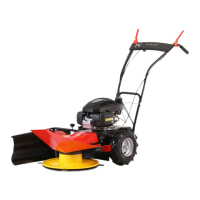
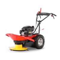
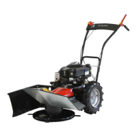
2. Take hold of the machine on the front L and rear M grasp points and take it out of the box.
3. Lift and turn the handlebars N on
"!L
and put them on the frame as per
"!LR
step ^L (choose one of three openings in
the handlebars and one of two openings in the frame to set the handlebars height). Install the handlebar bolt as per
"!LR
^L, place the flat washer and tighten the handlebars well using the wing nut. 0"%."%%
"&_%.%&&@Take the draw bands out of the bag and fix the cables to the handlebars
where the bending of the handlebars tube ends. Two pieces of the draw bands sufficient for cable fixing; cut the free ends of the
draw bands.
4. As per
"!LR
^M - prepare a bolted joint in the opening in the right rear part of the frame, don't tighten it. Put the right
(bigger) part of the cover M %-%"".&"&". as per ^M; the bolts
and in the frame must fit in the grooves in the cover. Tighten the bolted joint by hand. Don't tighten the jointed bolt
for now. Fix the right part of the cover using the bolted joint as per ^N and tighten it by hand.
5. As per
"!LR
^O - prepare a bolted joint (marked with an arrow) in the left rear part of the frame and put the left cover
N on the machine frame toward the rear. Fasten the cover N to the frame using the other bolted joint . Tighten both bolts by
hand. Connect both halves of the cover in the front part as per ^P using the bolted joint . Tighten the bolted joint .
6. Next steps differ based on the type of the handle.
a) ,%&%) As per
"!LR
^V - put the handle holder O on the left cover bracing and fasten it using two bolted
joints . Jam the rubber handgrip P on the fastened holder.
b) -) As per
"!LR
^W - fasten the strap Y with a bolt from the left side to the left cover using the bolted joint (.
Place the nut with the washer from the right side on the opposite side of the cover than the strap. Tighten the bolted
joint (, so that it is possible to move the strap freely.
7. Tighten all the bolted joints , and from steps ^M, ^N, ^O, ^P and ^V! Particularly check the tightening of the
bolted joints marked as per ^Y.
8. As per
"!LR
^S - put the rear (shorter) side screenS on the shorter part of the screen holder and the side (longer)
screenV on the longer part of the screen holder. Pass the draw bands through the openings in the screen holder and secure
both screensV andS against sliding by pulling the draw bands. Cut the free ends of the draw bands. Put the shorter part of
the screen holder into the opening in the frame. Tighten the fixing bolt W as per
"!M
and check that the side screen can't fall
out spontaneously.
3.4.2 PUTTING INTO OPERATION
(&%
85
".%%1@01;11&-%&!
0"1&%&-.%&(according to various national rules)!
3.4.2.1 STARTING UP THE ENGINE
"%%%i.%%-"&1-&.%."1!(%%
-"&&1-.-%!
Cold (first) engine start differs as per engine manufacturer. The engines equipped with a mechanical choke (Z&and )
require, similar as older cars, starting by means of a choke which is switched on by the accelerator lever
"!Y
. The automatic choke of the
` engines is activated based on the engine temperature and does not require any interference by the operator.
We distinguish starting according to the way the engine starts spinning:
% – By pulling the manual starter cord.
%"<""%= - By pressing the button on the start panel.
C;"%%LV&LS
"!M
-&..<1
-&&%=@
1.%%%%&.%--%1"@-.%
--%1!
The following chapters describe the individual differences in starting. The accelerator lever positions (L=0H, M=,*, N=,]
and O=ZH) are described in
"!Y
. All four described main positions are locked by a simple stamp-projection system in the lever
body. The functions of the buttons on the switch (0H , L and 0Q0) are described in
"!W
.
3.4.2.1.1 ELECTRIC STARTER ENGINE
A modern and at the same time the easiest way to start the engine. The battery also serves as a key to the machine and is therefore
also a safety device against accidental starting of the engine.
0"&1""%1&1%&-.
!
0"&&"&
86
1!
0.a&-&&&%-&!
.";""""""&"&.&%%&.
-%!
1.
"!W
- On the start panel, press the middle button marked L.
YP
Multilingual manual is part of the cutter.
YV
Charging the battery is described in the engine operating instructions.
NS
Q#RSMRML